


Twenty amperes is the workhorse final-circuit rating — chosen from load evidence, conductor calculation, curve behavior, and fault duty, never from the old breaker’s label alone.
Contractors and panel builders use this rating for general receptacle circuits, small appliance branches, and dedicated loads where the schedule calls for a step above 16 A. The rating is only one line in a coordinated protection decision.
Important: This guide structures 20 A final-circuit selection for LV panels in line with MCB product scope in IEC 60898-1 and assembly grouping practice in IEC 61439-1. It cannot approve a curve, pole count, or breaking capacity where load data, conductor protection, grouping derating, or fault duty is missing — hold those inputs for engineering review before ordering.
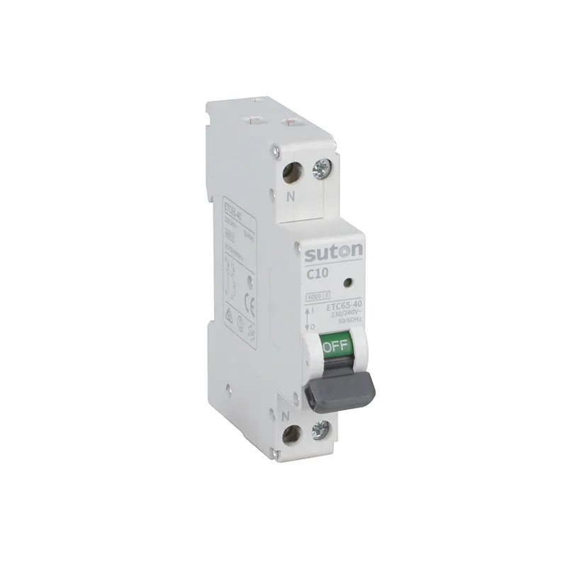
Part 1. Turn a 20 amp breaker request into schedule inputs
A 20 A order line is incomplete without the circuit function, design current, and conductor protection reference. Device-family fundamentals stay in the MCB breaker guide; this article owns the 20 A rating decision for final circuits.
| Selection factor | Why it matters for the panel | Send with quote |
|---|---|---|
| Circuit function and connected load schedule | grounds the load basis | yes |
| Conductor calculation reference | proves the pairing is protected | yes |
| Required rating step and curve | fixes trip behavior | yes |
| Pole count and neutral treatment | fixes circuit arrangement | yes |
| Breaking capacity vs fault study | fixes interrupting duty | yes |
| Residual integration requirement, if any | fixes device family | when applicable |
| Grouping, ambient, and enclosure conditions | fixes derating decisions | yes |
| Mounting interface, standards, quantity | fixes assembly scope | yes |
Procurement teams that compare only the amp number often receive devices that fit the label but fail curve, pole, or breaking-duty review at commissioning.
Part 2. Fix the load basis before the rating step
Take design current from the approved load calculation or appliance documentation. The breaker rating covers the load with the margin the design authority accepts, without exceeding what the conductor calculation will support.
Uprating from 16 A to 20 A is not a like-for-like swap — it is a design change that requires conductor recalculation and design-authority sign-off. The replacement workflow and risk language are covered in the breaker replacement guide.
Part 3. Coordinate the conductor calculation with the breaker
The 20 A rating must stay within the conductor’s corrected capacity under the project rules — not the other way around. Treat the calculation as the authority and the breaker marking as the protective ceiling that sits on top of it.
| Project input | Review question for the 20 A row |
|---|---|
| Connected load and utilization | Does design current justify 20 A rather than 16 A? |
| Cable route and installation method | What capacity basis does the route allow? |
| Ambient and grouping corrections | Does derating still support the pairing? |
| Run length | Do voltage-drop and fault-loop checks pass? |
| Applicable installation rules | Which standard governs the calculation? |
No national gauge table belongs in this article. Attach the calculation reference to the schedule so a future load change triggers review instead of silent uprating.
Part 4. Choose the tripping curve from documented load behavior
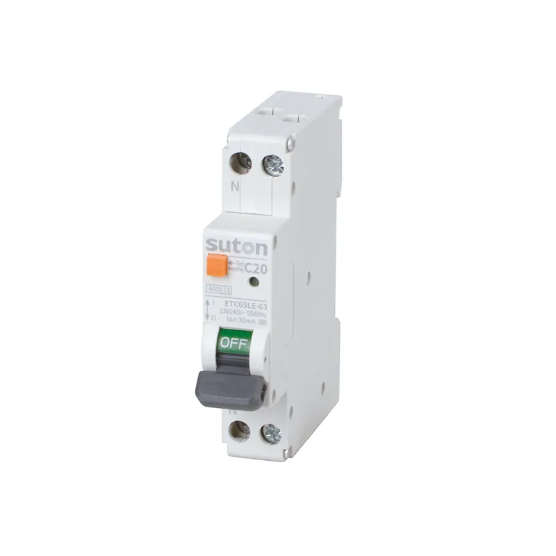
Curve choice follows documented inrush and load behavior, not habit. Motors, transformers, and electronic loads can draw start-up currents well above running values; a correctly rated breaker with a fast instantaneous band can trip on that inrush.
Match the curve to the load evidence instead of uprating to silence trips — uprating removes conductor protection margin and converts a nuisance into a hazard. Persistent tripping still deserves diagnosis; element degradation, wiring faults, and genuine overload all masquerade as inrush. Use the circuit breaker trip guide for structured investigation steps.
Part 5. Account for grouping, ambient derating, and nuisance trips
Grouped devices and elevated enclosure temperatures can require derating decisions that affect both breaker selection and conductor capacity. Record grouping assumptions on the schedule and in the panel dossier so later additions do not silently exceed the approved thermal budget.
Where several 20 A circuits share an enclosure route, the design authority should confirm that the assembly arrangement still supports the documented loading and protection scheme. Assembly context follows IEC 61439-1 integration practice; exact derating data remain model-specific and must be confirmed from manufacturer instructions.
Part 6. Route a documented 20 A breaker inquiry
Send with the inquiry:
- circuit schedule with the 20 A row and connected-load documentation
- conductor calculation reference and installation method summary
- required curve, poles, and breaking capacity vs fault study
- residual integration requirement, if any
- grouping and ambient assumptions used in the design
- mounting interface, applicable standards, and quantity
Require suppliers to declare the exact offered marking, curve, poles, breaking capacity, and installation instructions against the controlled schedule. Hold the engineering decision when conductor protection or fault-duty evidence is incomplete.
Fit Boundary: this guide structures 20 A final-circuit selection inputs. It does not perform conductor calculations, does not decide which regional rating ladder applies, and cannot approve replacing a 16 A device with a 20 A one without recalculation and design-authority sign-off. Close those gaps before pricing.
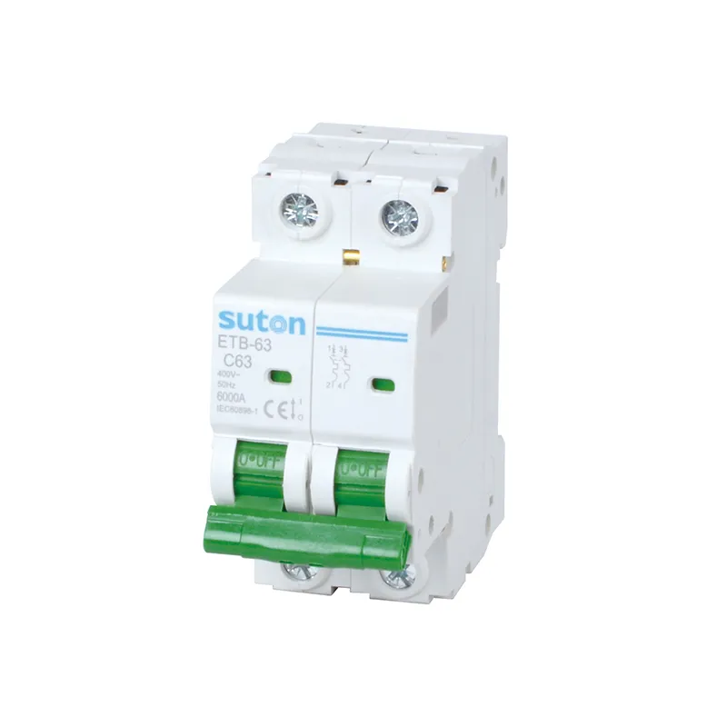
For a product recommendation starting point, review SUTON’s ETC65-40 series MCB route for general modular branch duty and the ETB-63 series high-breaking MCB route where higher interrupting duty is documented. Curves, poles, and breaking data are model-specific — confirm datasheets against the schedule, then send the circuit documentation through Contact SUTON for a documented review.
Final-circuit discipline on active sites
Treat every 20 A row as a paired decision: breaker rating plus conductor calculation reference. Facilities that inherit only the amp label tend to uprate silently when loads grow; facilities that inherit the pairing review the row in minutes.
After any unexplained trip, record connected load, recent additions, and ambient conditions before reset or replacement. Patterns across records distinguish inrush mismatch from genuine overload or a wiring fault.
When the panel expands, re-check grouping assumptions before adding ways. A new circuit in the same duct or enclosure can change the thermal picture for existing 20 A positions.
FAQ
What is a 20 amp breaker used for?
General final-circuit duty — receptacle branches, small appliance circuits, and dedicated loads — with the documented load basis as the rating anchor.
What wire size does a 20 amp breaker need?
Size the conductor from the project calculation — installation method, ambient, grouping, cable construction, and route length all participate; publish no universal gauge here.
Which tripping curve should a 20 amp breaker have?
The curve that matches documented load and inrush behavior at the correct rating — not a larger rating chosen to stop nuisance trips.
Why does a 20 amp breaker trip repeatedly?
Overload, inrush mismatch, wiring faults, and degraded loads can all cause trips; diagnose before uprating or swapping curves by habit.
Can a 20 amp breaker replace a 16 amp breaker?
Only after the conductor calculation and connected-load review are re-approved; raising the marking without that work removes cable protection margin.
What data belongs in a 20 amp breaker RFQ?
Provide the circuit schedule, load basis, conductor calculation reference, curve, poles, breaking capacity, residual integration, mounting, standards, and quantity.