DC breaker temperature derating means applying the selected manufacturer's temperature-related limits when determining usable current or settings in the actual installation. For a PV enclosure, the relevant air temperature can differ substantially from a nearby weather reading. Use the exact breaker's reference conditions, derating instructions, trip-unit characteristics and enclosure assessment. There is no universal percentage that safely converts every catalogue current rating into an outdoor PV rating. Do not increase a breaker setting to solve heat-related trips without first checking conductor protection, connections, loading and the complete thermal environment.
Identify which temperature the document means
A datasheet may refer to ambient air around the device under stated test or installation conditions. That is different from the outdoor temperature reported by a weather service, the surface temperature of the enclosure or a thermal-camera reading of a terminal. Before applying any correction, identify the manufacturer's intended measurement and reference condition. Confusing these temperatures can produce a precise-looking calculation with the wrong input. Record where the design temperature applies and how it was established.
For an outdoor combiner, enclosure color, direct sun, ventilation, mounting location and internal heat sources can influence the air around the breaker. The hottest relevant period may not coincide exactly with the peak outdoor reading. Use the project's accepted thermal assessment and appropriate measurements where required. A single reading taken with the door open does not necessarily represent the closed enclosure in service. State the conditions clearly so that another reviewer can judge whether the chosen input is appropriate.
Separate normal derating from an overheating defect
Derating accounts for declared operating conditions. It is not a justification for ignoring an abnormal hot connection, discoloration, damaged insulation or an unexplained odor. These observations require investigation through the site's safety procedure. A loose or unsuitable termination can create localized heating that is not solved by applying a general ambient correction. Likewise, an enclosure cooling problem can affect several components beyond the breaker, so the response should consider the complete assembly.
Do not compare terminal temperature directly with an air-temperature derating table unless the instructions expressly support that comparison. Thermal imaging can be useful within a qualified inspection program, but interpretation depends on load, surface properties, access and the equipment involved. Keep observations, load conditions and inspection findings together. If equipment condition is uncertain, qualified personnel should determine the appropriate response rather than treating a generic online temperature threshold as an authorization to continue operating.
Obtain the exact manufacturer's correction data
Request the applicable current-versus-temperature information for the exact model, trip unit, pole arrangement and installation conditions. A curve for a similar frame or another manufacturer's product is not transferable evidence. Confirm the reference temperature, allowed range and any restrictions on interpolation. If the instructions provide only discrete entries, ask how intermediate conditions should be handled. Do not extrapolate beyond the declared range to create an apparent rating for a more severe environment.
Electronic and thermal-magnetic trip units can have different characteristics, and neither description alone establishes the usable installation current. Terminals, conductors, accessories and the complete device still have thermal limits. Ask whether the published data assumes a particular enclosure, free-air mounting or other test arrangement. Keep the response with the equipment schedule. A sentence saying “temperature compensated” should prompt a request for its scope rather than ending the thermal review.
Build the enclosure thermal input sheet
| Thermal input | What to record | Why it matters |
|---|---|---|
| Temperature basis | Location and method for design air temperature | Avoid confusing weather, surface and device ambient |
| Device identity | Exact model and trip unit | Correction data can differ between products |
| Reference conditions | Manufacturer conditions and permitted range | Use only applicable correction method |
| Enclosure | Sun exposure, ventilation and internal sources | Account for actual air around the device |
| Connections | Conductor and terminal requirements | Do not hide a local overheating defect |
| Protection | Approved settings and conductor limits | Derating does not authorize loss of protection |
| Verification | Load and measurement conditions | A mild-weather test may not represent design duty |
The sheet should identify both the input and the supporting evidence. It is acceptable to record an unresolved temperature assumption as an open design item; it is not acceptable to replace it with a convenient weather number and mark the review complete. For supplier enquiries, include the enclosure layout and expected loading. That allows the manufacturer to state whether its published correction data applies directly or whether a further application assessment is required.
Work through a hypothetical correction carefully
Suppose a project requires a usable continuous current of 80 A and the exact manufacturer's applicable instructions provide a correction factor of 0.8 for the accepted conditions. A preliminary arithmetic check would require a reference current of at least 80 divided by 0.8, or 100 A. These figures are hypothetical and are not a SUTON rating or a universal PV design rule. The calculation only illustrates how a documented factor might be used when the instructions permit that method.
That arithmetic does not authorize a 100 A protective setting for an 80 A conductor. The designer must still verify conductor protection, trip characteristics, equipment limits and all applicable design rules. A larger frame with an appropriate trip unit might be one option, while a different enclosure arrangement might be another. Compare the complete solutions using actual data. If the manufacturer's method specifies settings differently, follow that method rather than forcing it into the simplified example.
Evaluate neighboring devices and connection space
Breakers operate inside an assembly. Adjacent protective devices, busbars, cable bundles and auxiliary supplies can contribute heat or restrict air movement. Review the proposed layout rather than checking the breaker in isolation. Required spacing and terminal access should follow the relevant equipment instructions. Leaving an arbitrary gap because it looks generous is not evidence that the enclosure meets its thermal requirements. Where ventilation is proposed, consider its effects on environmental protection and maintenance as well.
Conductor selection and routing deserve the same attention. Confirm material, size, terminal compatibility, insulation limits and the approved tightening procedure. Do not treat a larger conductor as an automatic cure for every temperature problem; the connection must remain within the terminal's accepted range and the enclosure must accommodate its bend radius. Review accessories and external links as part of the arrangement. A thermally acceptable device can still be incorrectly integrated if its connection conditions are overlooked.
Distinguish current derating from voltage assessment
Temperature-related current assessment and PV maximum-voltage assessment answer different questions. High enclosure temperature may affect usable current or operating behavior according to the product instructions. Cold module conditions can affect the array voltage calculation. Do not apply a current correction factor to voltage or assume a warm enclosure removes the need to check cold-corrected string voltage. Both reviews need their own inputs, evidence and acceptance criteria.
Use the guide to PV string voltage and breaker rating for the voltage worksheet and PV MCCB selection for the complete purchase schedule. The overall solar PV breaker selection guide connects these checks with current, fault duty and installation requirements. Cross-referencing separate worksheets makes the engineering basis easier to review and avoids hiding several unrelated assumptions inside one unexplained safety factor.
Review the actual SUTON product evidence
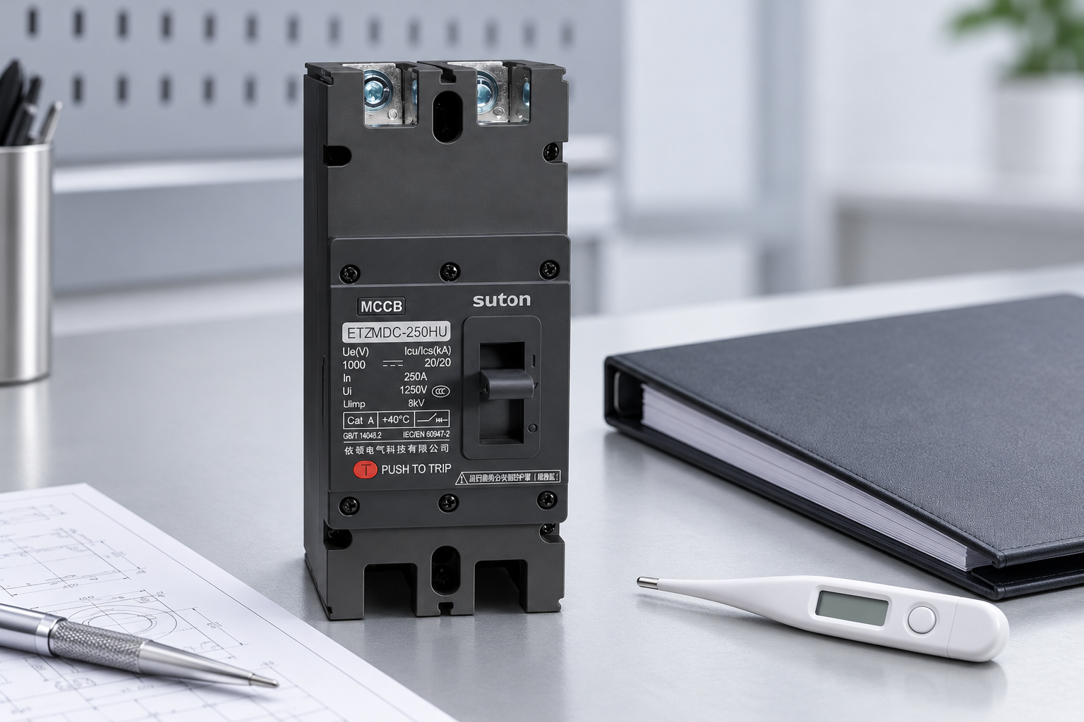
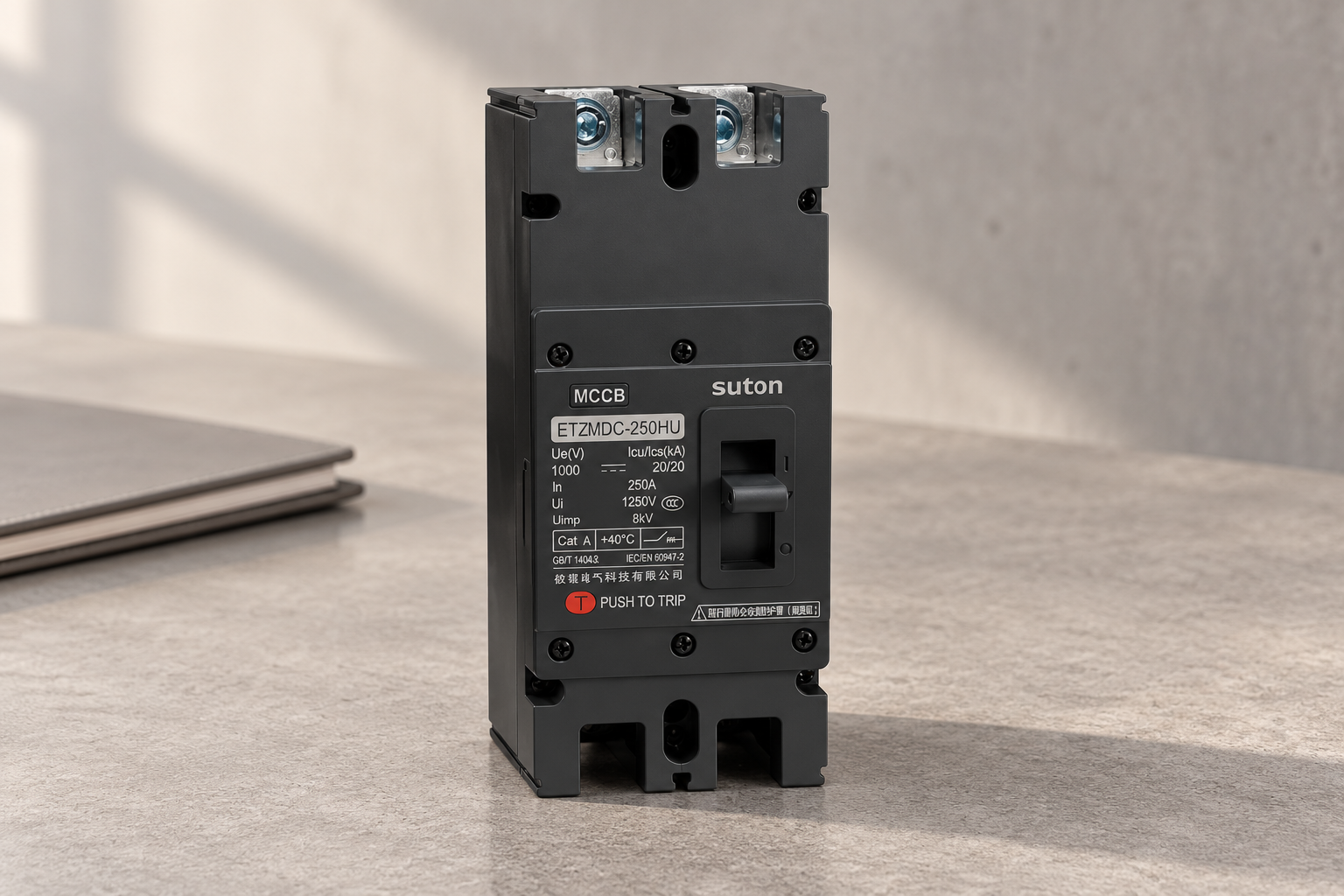
The SUTON ETZM PV molded-case DC breaker provides an appropriate product starting point for this enquiry. The images show its actual exterior for identity and documentation review. They do not demonstrate a temperature test, establish a derating curve or certify enclosure performance. Request the exact model's current documents and describe the proposed enclosure conditions. Do not infer an application limit from a photograph of a label without the full instructions and configuration.
Ask the supplier to state the reference conditions, applicable correction method, trip-unit details and any enclosure or mounting restrictions. Include the accepted design current, conductor data and expected internal temperature. If a different model is suggested, repeat the comparison using that model's evidence. Retain the response and the design calculation together so that a later replacement or enclosure modification does not silently lose the assumptions that made the original selection acceptable.
Verify the installation under representative conditions
Commissioning and later inspection should follow an approved procedure performed by qualified personnel. Record loading, enclosure condition, weather context where relevant and the measurement method. A successful short test under mild conditions does not prove suitability for the hottest design condition. Conversely, a trip should trigger a structured investigation instead of an automatic increase in setting. Compare the actual installation with the accepted thermal assessment and identify deviations before deciding on corrective action.
The national laboratory overview of PV DC systems provides useful context on PV operating conditions. The IET guidance on PV switching configuration reinforces the need to use declared application conditions for the selected equipment. Neither provides a universal SUTON derating factor. Obtain that information from the exact product documentation and retain the project-specific acceptance record.
Frequently asked questions
Is outdoor air temperature enough for derating a PV breaker?
Not necessarily. Determine the temperature relevant to the manufacturer's instructions, which may be the air surrounding the device inside the enclosure. Direct sun, internal heat and ventilation can make that different from a weather reading. Use the accepted enclosure assessment and representative measurement conditions.
Can I use a standard twenty-percent derating for every breaker?
No universal factor is established here. Obtain the exact model's correction data and follow its stated method and conditions. A factor from another product, a simplified example or an unrelated installation is not adequate evidence for the selected device's usable current.
Should I raise the current setting if the breaker trips in hot weather?
Do not change it without a protection and thermal review. Investigate load, connections, enclosure conditions and device condition first. Any revised selection or setting must continue to protect the intended conductors and equipment and remain within the approved manufacturer and project requirements.
Educational video
How do solar panels work? – Richard Komp by TED-Ed. This independent TED-Ed lesson explains how photovoltaic cells generate electricity. It supports the PV-source context; it does not approve breaker wiring, sizing, thermal limits or a maintenance isolation procedure.