


RCD protection is an installation-level strategy — not a single device label. It defines protection goals, circuit zones, grouping, selectivity between levels, and the testing regime that commissioning will audit later.
Device selection implements the plan; skipping the plan forces a second procurement cycle after nuisance tripping, selectivity failure, or an inspection finding. Start with the single-line diagram and circuit schedule, name each zone’s goal and rule reference, estimate standing leakage per group, and only then map device families to roles.
Important: This guide plans residual protection for LV distribution panels in line with assembly integration practice in IEC 61439-1. It cannot set sensitivities or zone boundaries where load data, earthing arrangement, or applicable rules are absent — hold those inputs for engineering review before pricing.
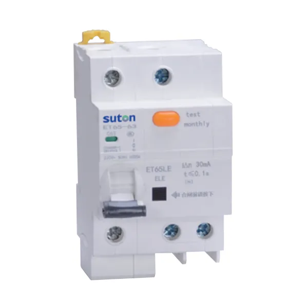
Part 1. What is RCD protection, beyond a device?
Ask “one residual device for the board, or one per circuit?” and you are asking a strategy question, not a product question. RCD protection is the installation-level plan that decides which circuits are protected, to what goal, in which groups, and with what testing regime. Projects that skip the plan buy devices twice: once from the catalogue, and again after nuisance tripping or a failed inspection forces a redesign.
Part 2. Which protection goals drive the plan?
Each zone in the plan should name its goal, because the goal drives sensitivity and arrangement decisions that a label never captures.
| Protection goal | Typical planning consequence |
|---|---|
| Additional protection for people | high-sensitivity devices close to final circuits |
| Fault protection support | sensitivity and disconnection coordinated with earthing system |
| Fire-risk reduction | moderate-sensitivity devices on selected distribution zones |
| Equipment or process continuity | grouping that limits outage spread on a trip |
Which circuits must be protected is set by the applicable local installation rules and the design authority. Record the rule reference per zone in the schedule rather than importing another project’s assumptions.
Part 3. How should circuits be grouped into zones?
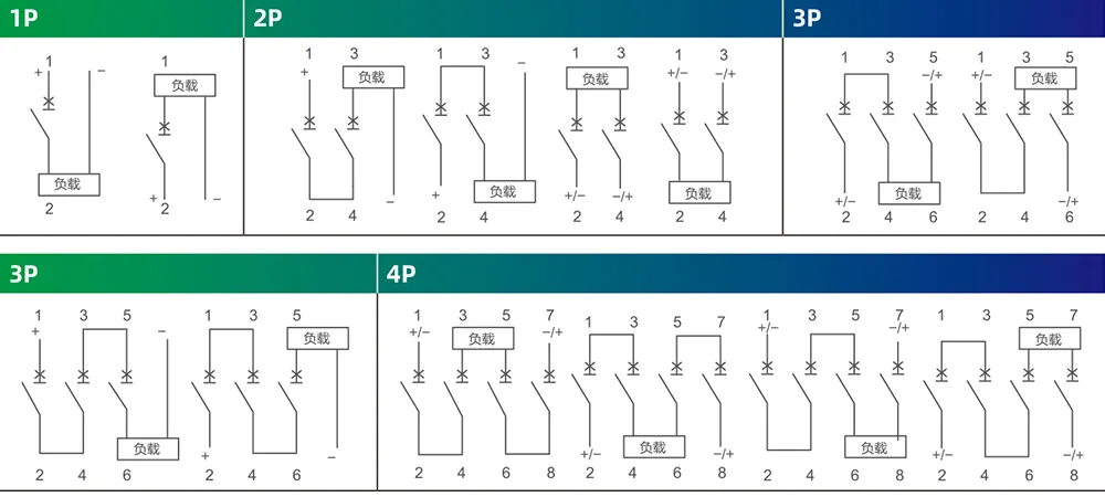
Grouping is a budget exercise. Every circuit contributes standing leakage, and a group shares one device’s tripping threshold; too many circuits per device produces trips with no fault present. Estimate the leakage per circuit from load documentation, then size groups so the standing total stays comfortably below the device sensitivity.
Grouping also fixes the outage consequence. A trip on a group device removes every circuit in the zone, so life-safety, alarm, or continuity-critical circuits usually justify their own device. Draw the zones on the single-line diagram before any purchasing conversation starts.
Part 4. How is selectivity achieved between RCDs?
Where residual devices sit in series — a group device upstream, circuit devices downstream — an unplanned arrangement trips the upstream device first and blacks out the zone. Selectivity needs deliberate choices: sensitivity steps between levels, time-delayed characteristics upstream where the design permits them, and manufacturer coordination data to confirm the pairing.
Treat selectivity claims as data, not as marketing. The confirmation belongs in the panel dossier next to the fault study, because commissioning tests and later service calls will both interrogate it.
Part 5. Which device roles implement the plan?
Once zones exist, device families take roles: group protection at distribution level, combined residual-plus-overcurrent devices on final circuits, and molded-case residual families where feeder ratings demand them. Device-level selection steps live in the residual current circuit breaker guide and the RCBO breaker guide.
Waveform classification is a separate decision layered on each zone. Where converter-fed loads appear, screen them per circuit — the Type A RCD guide explains the classification boundary that the schedule must record.
Part 6. Route an evidence-based SUTON inquiry
Send with the inquiry:
| RFQ input | Why it matters |
|---|---|
| Zone map on the single-line diagram | shows what each device protects |
| Circuits, loads, and leakage estimates per zone | validates the grouping budget |
| Protection goal and rule reference per zone | ties sensitivity to purpose |
| Required sensitivities and classifications | fixes device duty |
| Selectivity expectations between levels | demands coordination data |
| Testing regime and record format | fixes commissioning scope |
| Mounting, standards, quantities | fixes assembly scope |
Fit Boundary: this guide plans residual protection for LV distribution panels. It does not decide national rule applicability, does not replace a protection study, and cannot set sensitivities where load data, earthing arrangement, or rule references are missing. Escalate those gaps to the design authority before the plan is priced.
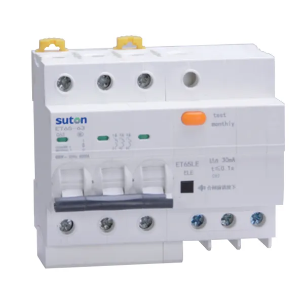
As a product recommendation starting point once a zone plan is approved, review SUTON’s modular DIN rail products for final-circuit and group devices, and the ETM3EL series electronic residual current circuit breaker route where feeder-level residual protection is being considered. These public routes do not fix sensitivity, classification, or coordination for any zone. Send the zone map and circuit schedule through Contact SUTON for a documented review.
Testing regime and lifecycle records
Write the testing regime into the plan on day one. Commissioning verifies device markings against the schedule, exercises each device with the authorized method, and archives results in the panel dossier. Periodic verification then repeats on the interval set by the applicable rules and the facility’s own risk decisions.
Keep the zone map current. Every added circuit changes a leakage budget; every load swap can change a classification decision. A dated revision block on the zone map turns those changes into reviewable events instead of silent drift.
Service events deserve the same discipline. After any unexplained trip, record the zone, the connected loads, and the weather or switching context before resetting. Patterns across records distinguish a genuine fault from a grouping budget that has quietly filled up, and they tell the next project what to plan differently.
Hand the complete package — zone map, schedule, coordination data, test records, and revision history — to the panel owner at takeover. Facilities that inherit the plan maintain it; facilities that inherit only a board full of devices tend to rebuild the strategy from scratch at the first inspection, at a much higher cost than the original planning effort.
FAQ
What is RCD protection?
It is the installation-level strategy for residual-current protection — goals, zones, grouping, selectivity, and testing — which devices then implement.
Which circuits need RCD protection?
That is set by the applicable local installation rules and the design authority; record the rule reference per zone instead of assuming a universal list.
How should RCD protection be grouped in a panel?
Group circuits so standing leakage stays comfortably below the device sensitivity, and give continuity-critical circuits their own device.
How is selectivity achieved between RCDs?
Step sensitivities between levels, use time-delayed characteristics upstream where permitted, and confirm pairings with manufacturer coordination data.
How often should RCD protection be tested?
Follow the interval set by the applicable rules and the facility’s risk decisions, and archive every result in the panel dossier.
What data belongs in an RCD protection RFQ?
Provide the zone map, circuits and leakage estimates, goals and rule references, sensitivities and classifications, selectivity expectations, testing regime, and quantities.