


Breaker replacement is safe only when the new device preserves protection duty, electrical ratings and physical interface—not when it merely shares the old breaker’s amp marking. Panel builders should isolate the circuit, identify why the old device was removed, and verify voltage, poles, trip characteristic, breaking capacity and frame compatibility before ordering a replacement.
For trip diagnosis before a swap, use the circuit breaker trip guide. For device classes, use the circuit breaker types guide.
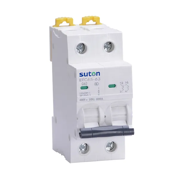
Part 1. When is breaker replacement justified?
A breaker should not be treated as a consumable part after every trip. Replace it only after inspection identifies mechanical damage, unacceptable contact wear, failed test results, an obsolete frame with no approved service path, or a design change that genuinely requires a different protective device.
First distinguish a fault in the circuit from a fault in the breaker. A breaker that trips repeatedly may be responding correctly to overload, leakage, inrush or short circuit. Replacing it with a larger frame can hide the fault and reduce conductor protection.
| Observation | First action | Replacement decision |
|---|---|---|
| One overload trip during temporary work | Check load and curve | Usually no replacement |
| Instant repeat trip | Isolate and test for short circuit | Replace only after fault investigation |
| Heat discoloration or damaged terminal | Inspect conductor and torque | Replace device if damage confirmed |
| Design current or fault level increased | Recalculate protection study | New device may be required |
Part 2. Which ratings must match?
The old marking supplies starting data, not a complete purchasing specification. Verify the following on the installed device, schematic and fault study:
| Parameter | Why it matters for breaker replacement |
|---|---|
| Voltage Ue | A device must be rated for the system voltage and AC/DC duty |
| Rated current In | Must protect the cable and carry design load |
| Breaking capacity Icu/Icn | Must exceed prospective fault current at that location |
| Poles and neutral treatment | Affects isolation and wiring arrangement |
| Trip curve or trip unit | Controls inrush tolerance and coordination |
| Frame and terminal type | Determines physical and conductor compatibility |
If original documentation is unavailable, record clear photos of the nameplate, terminals and panel position. Do not infer curve or Icu from a handle color or a generic catalogue image.
Part 3. Why does fault duty matter?
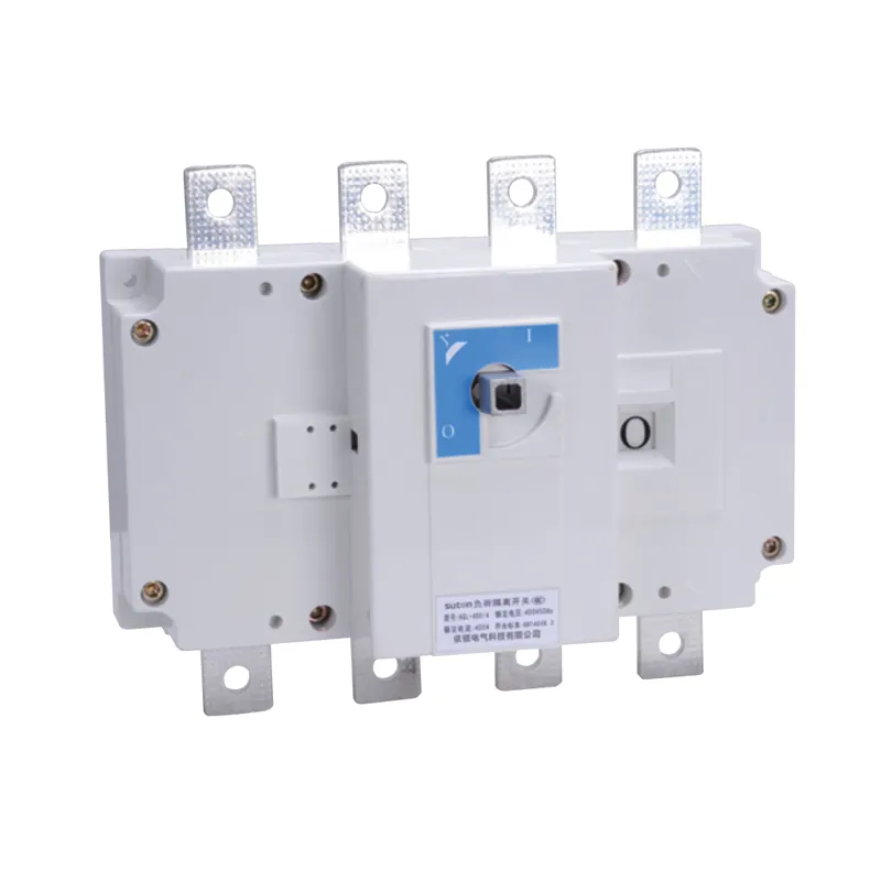
The replacement breaker’s interrupting capability must suit the prospective short-circuit current at its terminals. A device that matches nominal current can still be unsafe if its Icu/Icn is lower than the calculated fault level.
Fault duty differs across one panel. The main incomer may see more fault current than a long final circuit, while generator sources, transformers and parallel supplies can change the available current. Verify the exact voltage, source configuration and location in the single-line diagram before selecting an MCCB or MCB frame.
Use the main switch selection guide for incomer context. For feeder replacements, retain upstream/downstream coordination: a new device should not cause the entire board to trip before the affected branch clears.
Part 4. How do frame and mounting details affect replacement?
“Same size” is not a technical interface standard. Check:
- DIN rail, plug-in, bolt-on or fixed mounting method;
- line and load terminal orientation;
- busbar finger or stab geometry where used;
- enclosure depth, phase barriers and handle clearance;
- accessory interfaces for shunt trip, auxiliary contacts or door interlocks.
The DIN rail mounting guide helps with modular devices, but a DIN rail label does not establish cross-brand mechanical or busbar compatibility. For molded-case devices, match the documented frame or use a qualified panel modification process.
Part 5. Which replacement mistakes create risk?
Common errors include:
- Matching only amperes. In alone does not verify Icu, curve, poles or voltage.
- Upsizing after a trip. This can leave a cable unprotected when the root cause is overload.
- Changing curve without load data. A higher magnetic threshold can mask a fault; a lower one can cause nuisance trips.
- Forcing a near-fit into a busbar. Contact pressure and phase spacing cannot be assumed.
- Ignoring the original trip cause. Leakage or loose connections can persist after any replacement.
Document the original failure condition. This gives the replacement supplier enough information to recommend a compatible route instead of guessing from a single photo.
Part 6. What should be checked before energizing?
Follow an approved lockout and verification procedure for the site, then complete a controlled commissioning check.
| Check | Purpose |
|---|---|
| De-energized isolation confirmed | Protects personnel during replacement |
| Terminal and conductor inspection | Finds heat damage or incorrect wire size |
| Torque and phase identification | Prevents loose or crossed connections |
| Nameplate comparison | Confirms voltage, In, poles, curve and Icu |
| Functional ON/OFF and trip test | Confirms mechanism and indication |
| Controlled load energization | Checks for unexpected trip or heating |
Fit Boundary
- Suitable when: device markings, fault level and mounting interface are known.
- Hold for engineering: missing diagrams, damaged busbars, unexplained repeat trips, or a change from AC to DC duty.
- Do not assume: that any same-amp breaker is an approved substitution.
Part 7. How do SUTON lines fit a replacement RFQ?
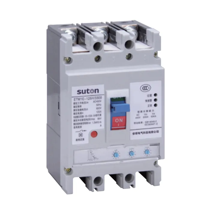
| Replacement position | SUTON starting point | Confirmation needed |
|---|---|---|
| Modular final circuit | DZ47 Series MCB | Curve, poles, voltage, Icn |
| Modular protection range | Modular DIN rail products | Rail/busbar and module details |
| Feeder or panel incomer | ETM3E intelligent MCCB | Frame, Icu, trip unit, terminals |
| Isolation section | ETGL load-break switch | Upstream overcurrent protection |
Send the old device photo, single-line position, voltage, In, Icu requirement, poles, trip curve, mounting details and quantity through Contact SUTON.
FAQ
When does a circuit breaker need replacement?
After confirmed mechanical or thermal damage, failed testing, an obsolete service path, or a documented design change—not simply because it tripped once.
Can I replace a breaker with the same amp rating?
Only after verifying voltage, poles, curve, breaking capacity, frame and mounting interface as well as rated current.
Why must I check breaking capacity before breaker replacement?
The replacement must safely interrupt the prospective short-circuit current at its installed location.
Can I change a breaker trip curve during replacement?
Only with verified load-inrush and coordination data; changing curve can cause nuisance trips or reduce protection.
What should be checked after a breaker replacement?
Terminal condition and torque, device markings, operation, insulation where applicable, and controlled energization under load.
What information should I send for a breaker replacement RFQ?
Nameplate photos, panel position, voltage, In, fault level, poles, curve, mounting style, diagram and quantity.