


A motor circuit protector clears short-circuit faults on motor branch feeders while coordinating with contactors and overload relays. Panel builders need documented FLA, fault level, and SCWR data—not a generic branch breaker line on the motor schedule. Align device choice with the single-line diagram and project standards (IEC or NEC where cited) without implying automatic code approval for any catalog SKU. Freeze motor list revisions on the quotation cover sheet before mechanical layout closes starter wireways.
Part 1. What does a motor circuit protector do in LV motor feeders?
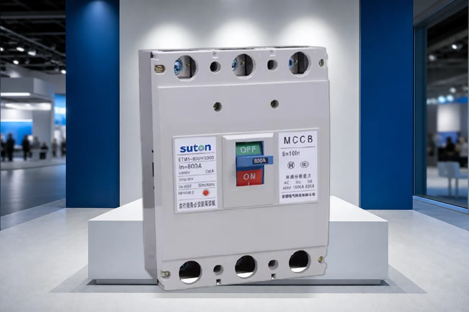
A motor circuit protector (MCP) provides short-circuit protection for motor branch circuits while coordinating with contactors and overload relays that handle running overload duty.
Contractors should treat the MCP as the branch short-circuit device on the motor schedule, not as a substitute for upstream feeder protection or for the overload relay that carries sustained motor overload duty.
Short-circuit duty versus overload duty
The MCP clears high-level fault current; the overload relay clears sustained motor overloads. Specifications should name both devices rather than assuming one breaker covers every motor duty.
Panel builders map the MCP to the single-line diagram branch that feeds the motor starter—not to general lighting or mixed-load feeders.
Where MCPs sit in the starter lineup
Typical lineups place the MCP ahead of the contactor and overload relay. Cable impedance and starter impedance affect prospective fault current at the MCP terminals and must appear on the fault study.
When starters are supplied in a factory-built assembly, confirm whether the MCP is included in the assembly SCWR rating or must be coordinated as a separate catalog device.
Part 2. How does an MCP differ from MCCB and motor starter combinations?
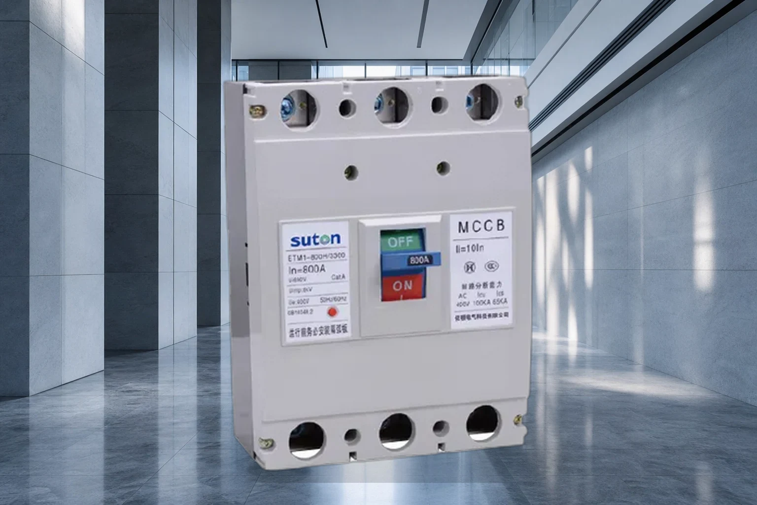
MCPs emphasize magnetic short-circuit protection with defined coordination to overload elements. A general-purpose MCCB may include thermal overload elements that overlap starter functions.
When consultants allow either an MCP or an MCCB with motor-rated instantaneous adjustment, document the chosen approach on the single-line diagram so field teams do not mix device types across duplicate feeders.
Instantaneous-only versus thermal-magnetic MCCB
Some motor branches use an MCCB with adjustable instantaneous pickup instead of a catalog MCP frame. Compare manufacturer coordination tables for the contactor and overload pair you specify.
Group motor installations
When several motors share protection logic, document whether the MCP protects one starter or a documented group—and whether spare starters are included in the group calculation.
Group motor calculations should list the largest motor FLA, the equivalent smallest motor contribution, and any spare starter the owner expects to energize during maintenance bypass operations.
Part 3. Which ratings should contractors verify before quotation?
Record motor full-load current, locked-rotor expectations, service factor, and prospective short-circuit current at the starter terminals before comparing MCP quotations.
Full-load and locked-rotor data
Motor nameplate FLA and code letter or locked-rotor data drive overload relay selection and MCP instantaneous pickup settings. Omitting service factor in the load list is a common cause of nuisance tripping after startup.
For variable-frequency drive applications, confirm whether the consultant assigns motor protection upstream of the drive or at the line-side disconnect feeding the drive cubicle.
Short-circuit withstand (SCWR) coordination
IEC and manufacturer guides reference short-circuit withstand requirements between MCP, contactor, and overload relay. Request coordination data at the stated fault level—not at a generic catalog default.
Voltage, poles, and enclosure
System voltage, number of poles, and starter enclosure IP rating should match the installation environment. Export panels should document whether the MCP is factory-wired inside the starter compartment or supplied loose for field assembly.
| Rating / data | Typical question it answers | Source |
|---|---|---|
| Motor FLA / LRA | Overload and instantaneous pickup | Motor nameplate / consultant |
| Fault level at starter | MCP interrupting duty | Fault study |
| Contactor / OLR pair | SCWR coordination | Manufacturer tables |
| Enclosure / IP | Environmental fit | Site specification |
Part 4. How should MCPs coordinate with contactors and overload relays?
A motor branch fault should clear at the MCP without welding the contactor or damaging the overload relay when coordination is correctly specified.
Request manufacturer time-current curves for the full starter combination at the fault level stated on the drawing revision you are building—not at a rounded value from an older study.
Time-current separation
Compare MCP instantaneous curves with overload trip curves and contactor SCWR ratings. IEEE 141 treats upstream fault data as a prerequisite before finalizing motor protection devices.
Single-line clarity
Drawings should show MCP, disconnect means, contactor, overload relay, and motor terminals as distinct components. Maintenance teams isolate using the device the O&M manual identifies—not an ambiguous branch breaker label.
When multiple motors share a panel, color-coded or numbered feeder labels that match the motor list reduce lockout errors during plant outages.
Part 5. What installation and wiring details affect acceptance?
Motor feeders introduce cable length, starter heat, and vibration that influence device selection and terminal torque requirements.
Conductor sizing and terminal temperature
Branch conductors must match MCP and overload terminal ratings. Record torque values and conductor classes on the test sheet handed over at energization.
Mechanical coupling and vibration
Industrial motor starters in vibrating plant areas may need reinforced mounting and phase barriers. Document inspection intervals when starters sit on equipment skids rather than wall-mounted panels.
Record ambient temperature near enclosed starters; thermal rise can affect overload trip margins when several motors restart in sequence after a plant-wide outage.
Part 6. Which standards apply when projects cite NEC or IEC?
Motor branch protection references vary by project. Cite the standard family the owner expects without implying automatic approval for any export catalog SKU.
IEC 60947-4-1 and motor-starter assemblies
IEC-oriented specs may reference contactor and starter coordination standards alongside MCP device data. Assembly-level documentation may be required when the starter is factory-built.
NEC Article 430 when cited on drawings
Where NEC Article 430 appears on motor schedules, map owner requirements for disconnecting means, overload protection, and branch short-circuit protection to the devices on your BOM.
Export panels may reference IEC motor-starter practices while the owner still expects NEC-style motor schedules—list both standard families on the handover index when dual references appear.
Part 7. Which RFQ and handover items should motor panels include?
Motor panel handover should connect protection settings to the motor list, not only to generic panel schedules.
Settings record and nameplate photos
Provide MCP pickup settings, overload dial positions, and contactor coil voltage on the commissioning record. Photograph motor and MCP nameplates for spares ordering.
Starter wiring diagrams
Include control-power routing, interlocks, and MCP terminals on as-built diagrams. Export projects still benefit from English circuit descriptions even when field labels use local language codes.
List spare heater elements, auxiliary contacts, and MCP trip units on the recommended spares table so procurement teams do not reorder from memory after the first outage.
| RFQ / handover item | Purpose | When to include |
|---|---|---|
| Motor list with FLA / service factor | Sets overload and MCP scope | Before purchase order |
| Coordination table (MCP / OLR / contactor) | Proves SCWR strategy | Design phase |
| Torque and test record | Proves installation quality | Before energization |
| As-built starter diagram | Maintenance isolation | At shipment |
Part 8. Which MCCB and isolator ranges fit typical motor branch panels?
After motor FLA, fault level, and starter coordination are fixed on the approved diagram, branch device selection narrows to molded-case and modular ranges that match your panel platform—not catalog photos alone.
ETM1 class MCCB for motor sub-mains
The ETM1 molded-case range suits higher ampacity motor feeders where adjustable instantaneous pickup and auxiliary contacts matter. Compare Icu/Ics at your stated system voltage against the fault study before freezing the bill of materials.
ETGL load-break isolator for motor disconnect
DIN-rail switch-disconnectors and load-break switches such as the ETGL(HGL) series provide visible isolation ahead of motor starters. Document whether the consultant requires isolator, disconnect, or lockable handle on the motor schedule.
When to involve factory engineering
Share the motor list revision, fault-study reference, and starter one-line before formal quotation. Factory engineering can align device curves, busbar cutouts, and export documentation with your panel BOM.
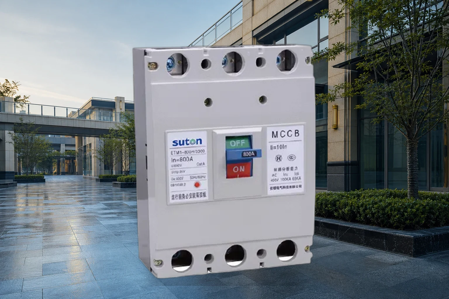
When your single-line diagram and load schedule are fixed, compare SUTON ETM1 Series MCCB and SUTON ETGL(HGL) Load Break Switch, explore application solutions, or review OEM/ODM capabilities. For datasheet alignment against your fault study, SUTON engineering support can review project parameters.
FAQ
What is a motor circuit protector used for?
A motor circuit protector provides defined protection or switching functions within a low-voltage distribution path, selected to match load, fault level, and wiring rules.
How do you select a motor circuit protector for a commercial panel?
Collect load schedules, fault studies, enclosure ratings, and coordination targets; match device curves to upstream and downstream protectors.
What is the difference between motor circuit protector and related protection devices?
Related devices may combine functions (e.g., overcurrent plus residual current); the specification should name required functions explicitly.
What standards apply to motor circuit protector in low-voltage assemblies?
IEC 60947 series and IEC 61439 assemblies are common references; U.S. projects also follow NFPA 70 (NEC) and local AHJ rules.
How does a motor circuit protector coordinate with upstream breakers?
Coordination requires aligned time-current curves so faults isolate at the intended level without unnecessary upstream trips.
What documents should panel builders request for motor circuit protector?
Request type test summaries, wiring diagrams, spare parts lists, and commissioning checklists suitable for your acceptance plan.
References