


A four-pole MCB request is a neutral-switching and feeder-position question — not a three-pole device with an extra module. Panel builders use the phrase when a three-phase plus neutral circuit needs documented pole duty, earthing context, and interruption evidence before a feeder or incomer device is released.
Start with the approved single-line diagram and circuit schedule. Record supply voltage, earthing arrangement, whether the neutral is switched or pass-through, breaking capacity at the device terminals, and upstream coordination references before comparing quotations.
Important: This guide structures four-pole MCB selection for low-voltage distribution panels in line with assembly integration practice in IEC 61439-1 and breaker product scope in IEC 60947-2. It cannot approve a device marking, neutral-switching category, or coordination result where system arrangement, fault duty, or upstream protection references are missing — hold those inputs for engineering review before procurement.
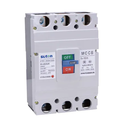
Part 1. Turn a four-pole MCB request into documented feeder inputs
Ask “which four-pole MCB for this feeder?” and you are asking for a controlled input set tied to a defined panel position. The same current label can represent different duties when the earthing system, neutral treatment, or upstream source changes.
| Selection factor | Why it matters for the panel | Send with quote |
|---|---|---|
| Supply voltage, frequency, and earthing arrangement (TT/TN) | fixes application and neutral reference | yes |
| Required four-pole switching category and neutral routing | fixes pole duty | yes |
| Rated current, trip curve, and thermal limit | fixes load duty | yes |
| Breaking capacity Icn/Icu at the device terminals | fixes interruption review | yes |
| Upstream incomer and downstream branch context | supports coordination review | yes |
| Busbar, terminal, and DIN rail mounting interface | fixes assembly scope | yes |
| Standards requested, accessories, and quantity | fixes approval and procurement batch | yes |
Projects that skip the table often receive quotations built on a pole-count label alone. That produces a second procurement cycle once neutral switching, fault duty, or coordination evidence is challenged on site.
Part 2. Match neutral switching to TT/TN context and pole duty
Determine whether the approved design requires all four poles to switch under load, whether the neutral is switched for isolation only, or whether a three-pole device with separate neutral link is documented. Do not infer neutral treatment from a product photograph or an abbreviated purchase description.
In TN systems the neutral is usually a defined reference; in TT systems earth-fault paths and RCD placement can change what switching the neutral achieves. Record the required arrangement consistently on the drawing, circuit schedule, and RFQ. Device-level breaker context lives in the circuit breaker guide; panel enclosure and way planning context lives in the circuit breaker panel guide; this article owns four-pole feeder inputs, neutral duty, and RFQ structure only.
| Arrangement question | Why it matters | Common mistake |
|---|---|---|
| Four-pole switching versus three-pole plus neutral link | fixes isolation and test scope | copying pole count from a previous job |
| Neutral conductor routing through the device | fixes measurement and maintenance access | assuming neutral is always switched |
| Feeder versus incomer position on the single-line | fixes fault level and selectivity | treating every four-pole device as a branch MCB |
| Phase identification and labeling | fixes inspection traceability | omitting neutral labels from the schedule |
Modular spacing and rail profile checks belong with the DIN rail guide when the four-pole device sits on a modular row rather than a molded-case feeder mount.
Part 3. Check fault duty at the feeder or incomer position
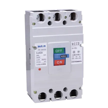
Breaking capacity and coordination must be assessed at the intended four-pole device terminals, not only at the main incomer. A feeder close to the transformer can see a different prospective fault current from a sub-feeder at the end of a long busbar run.
Capture source configuration, conductor route, upstream protective devices, and any parallel source arrangement in the technical review. Matching In values on different manufacturer datasheets does not demonstrate selectivity for the feeder combination under review. Archive the manufacturer’s time-current tables and type-test references for the specific upstream and four-pole pairing before approval.
Where the four-pole device protects a three-phase plus neutral feeder, confirm that the offered pole arrangement matches the switching category on the approved drawing. An ETM1-class molded-case route may be appropriate for higher feeder duty; a DZ47-class modular route may apply only where the schedule documents modular final-circuit or sub-feeder conditions — verify marking and instructions for the exact position.
Part 4. Plan four-pole layout, terminals, and busbar interface
Allocate rail or mounting space, phase spacing, neutral terminal access, busbar interface, conductor bend room, and labels before assembly. The panel drawing should preserve phase and neutral identification and make the four-pole position understandable during inspection and service.
Check exact terminal, busbar tooth, and mounting compatibility with the offered configuration. A device that satisfies the rating check but leaves no room for neutral tails, label space, or torque access can still fail the assembly review.
Reserve door clearance, operating handle access, and shroud space from the schematic before the enclosure layout is frozen. Four-pole modular devices consume more module width than their three-pole equivalents — confirm spare ways and comb-busbar alignment on the layout drawing.
Part 5. Prepare a controlled procurement comparison
Before any quotation is compared, reconcile the earthing arrangement, neutral-switching duty, conductor interfaces, enclosure conditions, and mounting method against the approved drawing. A shared comparison table makes missing evidence visible before assembly begins.
| Interface check | Why it matters |
|---|---|
| Single-line position and circuit identity | fixes where the four-pole device sits |
| Phase, neutral, and four-pole switching category | validates pole duty |
| Breaking capacity and coordination reference | validates interruption review |
| Busbar, terminal, and mounting fit | validates physical interface |
| TT/TN context and any RCD or earth-fault requirement | validates system reference |
| Standards requested and quantity | fixes approval and assembly scope |
Require suppliers to declare the exact offered marking, installation instructions, neutral-switching category, accessories, and exceptions. Hold the engineering decision when the required system arrangement or fault-duty evidence is incomplete — a quotation against an undefined feeder schedule cannot preserve the design intent.
Part 6. Route an evidence-based SUTON inquiry
Send with the inquiry:
| RFQ input | Why it matters |
|---|---|
| Approved single-line diagram and feeder circuit schedule | shows system position and neutral routing |
| Supply voltage, frequency, and earthing system (TT/TN) | fixes application conditions |
| Rated current, four-pole arrangement, and breaking-capacity requirement | fixes electrical duty |
| Coordination data and upstream protection reference | supports combination review |
| Busbar, terminal, mounting interface, and labeling requirements | fixes assembly scope |
| Standards requested, accessories, and quantity | fixes approval and procurement batch |
Fit Boundary: this guide structures four-pole MCB specification inputs for LV feeder and incomer positions in distribution panels. It does not decide national rule applicability, does not replace a coordination study, and cannot approve a device where neutral-switching duty, system arrangement, or fault-duty references are missing. Escalate those gaps to the design authority before the package is priced.
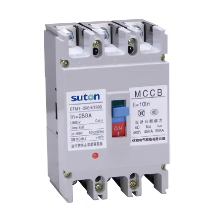
SUTON’s DZ47 Series MCB public route supports modular four-pole conversations after the buyer has defined the required function, neutral treatment, and project conditions. It is not treated here as proof that every listed configuration satisfies the feeder interruption duty, pole arrangement, or coordination evidence for a specific circuit. Where the schedule documents molded-case feeder duty, use modular DIN rail products and Contact SUTON to confirm whether an ETM1-class or DZ47-class route matches the approved marking.
Once the feeder schedule and single-line diagram are approved, send the controlled documents through Contact SUTON for a documented product-route review. Require each offer to answer the Part 1 table and keep the approved four-pole device schedule with the assembly record.
Feeder neutral handover and revision control
Treat the feeder circuit schedule, neutral-switching references, coordination records, and revision history as one handover package. Facilities that inherit the dossier can maintain and expand the panel with traceability; facilities that inherit only a pole-count label tend to rebuild the review from scratch at the first maintenance outage.
When sources, parallel feeds, or neutral links change, revise the single-line diagram and four-pole device schedule before re-energizing. An added feeder or changed TT/TN context can alter fault duty and neutral reference even when the catalogue rating looks unchanged.
After an unexpected trip on a four-pole feeder, note the circuit, connected load, neutral path, and recent switching context before reset. Repeated entries often reveal a coordination or neutral-switching gap rather than a random nuisance event.
FAQ
What is a 4 pole MCB?
It is a miniature circuit breaker with four poles, selected for a documented three-phase plus neutral circuit position, switching duty, and protective function.
When is a four-pole MCB required instead of three poles?
Use the approved design and device instructions to determine whether the neutral must be switched with the phases for isolation or system reference reasons.
Does TT or TN earthing change four-pole MCB selection?
Yes. Earthing arrangement fixes how the neutral is referenced and whether switched-neutral isolation is part of the documented duty.
Can a four-pole MCB serve as a feeder incomer?
Only when the schedule documents feeder or incomer duty, fault level, coordination, and physical interface for that position — not from pole count alone.
What breaking capacity does a four-pole MCB need?
It must exceed prospective fault current at the installed feeder or incomer terminals for the documented source arrangement.
What data belongs in a four-pole MCB RFQ?
Provide the earthing system, neutral-switching requirement, ratings, poles, fault-duty data, coordination references, interfaces, and quantity.