


1P+N vs 2 pole RCBO is a question about what the device senses, switches and protects—not just how many terminals appear on the front. A 1P+N RCBO may protect and switch the line while passing the neutral through a defined pole, whereas a two-pole device may switch and sense both conductors according to its design. Confirm the exact wiring diagram, neutral function, isolation objective, line/load direction and local rules before selecting or substituting either type.
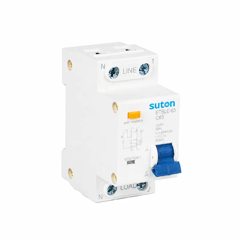
Decision table
| Question | 1P+N review | Two-pole review |
|---|---|---|
| What is sensed? | Confirm line and neutral sensing path | Confirm both conductors pass the sensor |
| What opens? | Confirm neutral switching behavior | Confirm simultaneous pole operation |
| Neutral protection | Check whether neutral is overcurrent protected | Check the exact pole function |
| Substitution | Verify diagram, dimensions and coordination | Verify diagram, dimensions and coordination |
Use the table as a screening aid, then verify each row against the exact product documentation and project study. The parent circuit-breaker guide gives broader context, while 2 pole vs 4 pole rccb and rccb neutral wiring errors cover related RCCB selection questions.
Compare sensing, switching and overcurrent functions
Read the manufacturer diagram for each candidate. Confirm which conductors pass through the residual-current sensor, which poles open on a trip, whether the neutral pole is protected against overcurrent and whether the neutral is switched or only passed through. A product description using “two-pole” does not prove that both poles have identical protection functions. Record the catalog code and terminal numbering.
Review the installation and isolation boundary
For a single-phase line-and-neutral circuit, draw source, RCBO, load neutral, protective earth and every bond. Check whether maintenance isolation requires the neutral to open with the line, and whether a transfer or multi-source arrangement changes that requirement. Do not use a 1P+N device as a generic replacement for a two-pole device without reviewing neutral behavior and the approved drawing.
Verify the substitution
Compare width, busbar compatibility, terminal capacity, accessories, test-button circuit, residual-current type, breaking capacity and coordination. Record the reason for the selected pole arrangement and repeat the test after installation.
Start with the installation duty
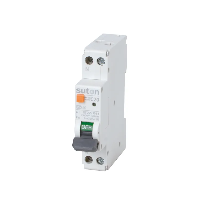
An RCBO combines residual-current protection with an overcurrent function, but the two functions still have different design questions. State the system voltage and frequency, phase and neutral arrangement, rated current, prospective fault current, earthing system, residual-current objective, required disconnection time, enclosure and operating mode. The exact catalog code, poles, curve, residual-current type, accessories and terminal arrangement then become part of the approval record.
Do not choose from a photograph or a short product label alone. Keep the single-line diagram, cable schedule, fault study, device coordination information, manufacturer instructions and commissioning record together. If the offered product differs from the study, treat the quotation as conditional until the responsible engineer reviews the change.
Use evidence and an RFQ checklist
Ask for the complete model code, rated current, voltage, short-circuit capacity, trip curve, residual-current sensitivity and type, pole arrangement, neutral treatment, line/load markings, terminal torque, accessories and test method. Ask which claims are tested for the exact combination and which depend on installation conditions. Record the datasheet revision with the purchase order.
IEC 61009-1:2024 gives general requirements and tests for RCBOs within its stated scope. HSE electrical-safety guidance reinforces competent work and safe isolation. These references do not approve a particular SUTON model or project; apply the adopted standard and manufacturer instructions.
Commission and preserve the as-left state
Before energization, verify identity, terminals, conductor routing, neutral path, barriers, labels, settings, test-button operation and isolation boundaries. Record the instrument, method, operating mode, measured result and drawing revision. A test button exercises a defined internal circuit; it does not replace inspection, insulation testing, fault verification or safe isolation.
After a load, cable, source, setting, firmware or accessory change, repeat the relevant review. Keep normal, standby, transfer, generator, bypass and maintenance modes visible. If evidence is missing, mark the item conditional and obtain engineering approval instead of assuming a similar-looking RCBO has the same behavior.
Review the circuit before accepting a quotation
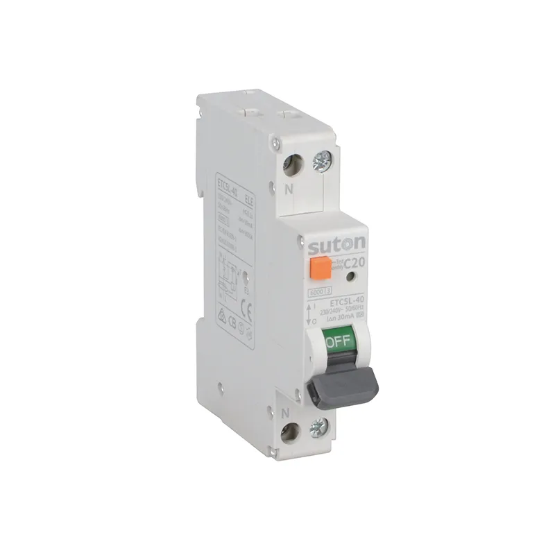
List each outgoing circuit, its conductor size and length, protective-earth arrangement, connected load, expected inrush and maximum fault current. Identify whether the circuit is single phase or three phase, whether the neutral is distributed, and whether the panel includes a busbar, comb connection or flexible link. These details affect the physical installation as well as electrical performance. Ask the supplier to state compatible terminal sizes, tightening torque, stripping length, accessory positions and enclosure conditions rather than relying on a generic catalogue image.
For a new panel, compare the RCBO schedule with the schematic, panel layout and cable schedule line by line. For a replacement, save a before snapshot of the existing device, model code, terminal positions, settings and date. A change that appears small—such as moving a feed to another busbar position or adding an auxiliary contact—can change the isolation boundary, neutral route or available fault duty. Record the reason for the change and the person who approved it.
Use controlled tests and clear acceptance criteria
Define the acceptance test before energization: visual inspection, conductor identification, connection check, protective-conductor continuity, insulation or leakage test where applicable, residual-current test, overcurrent function test where specified, and verification of labels and barriers. State which values come from the product manual, which come from the project calculation and which come from the local installation rules. A test result without its method and instrument range is difficult to audit.
When a test fails, keep the failure visible and investigate one variable at a time. Do not change the device type, setting, wiring and load simultaneously. Check whether the device is the quoted code, whether the neutral is routed through the intended sensor, whether the incoming and outgoing terminals match the diagram, and whether the source is in the expected mode. If the corrective action changes a drawing or setting, issue a revised document and repeat the affected tests.
Keep maintenance information usable
At handover, give the owner the final model code, rating, curve or characteristic, residual-current type and sensitivity, breaking capacity, pole arrangement, terminal diagram, accessory list, test result, drawing revision and maintenance limitations. Label the device and its circuit so a future technician can identify the isolation point without guessing. Where the device is part of a selective or backup arrangement, keep the coordination table with the panel record.
Reassess the selection after a transformer, generator, inverter, charger, motor drive, cable route, firmware, enclosure or source change. Also reassess after a repeated trip, unexplained test failure or a change in the local rules. A new device with a similar front label may have different sensing, switching, electronic supply or short-circuit behavior. Treat the replacement as a new technical decision until the evidence shows otherwise.
Supplier questions that close common gaps
- What exact model code and option package is being offered?
- Which terminals are line, load and neutral, and is reverse feed permitted?
- What residual-current type, sensitivity and delay are declared?
- What rated current and short-circuit capacity apply at the project voltage?
- Which backup, cascading or selectivity tables cover the proposed combination?
- What test method and instrument limits are required at commissioning?
- Which ambient, enclosure, busbar and accessory restrictions apply?
- What document revision should be retained with the purchase order?
Keep the acceptance record readable for procurement, commissioning and maintenance teams. If a value is conditional on a source, cable, enclosure or accessory, write that condition beside the value. A clear limitation is safer than a blank field that later appears to be approval.
For fault-duty decisions, keep both the maximum and minimum calculated values and state the calculation date. For wiring decisions, keep the terminal diagram and a photo of the completed panel where site rules permit. For testing decisions, retain the instrument identity and the exact procedure used.
Review the record whenever site conditions or equipment change, and date the review for traceability now.
Keep the final approval with the panel documents so future inspections can confirm the same assumptions, terminals, settings and test boundaries.
Product and related resources
Use the SUTON RCBO product page as a quotation starting point. The circuit-breaker types guide is the parent overview; the related guides below cover adjacent selection decisions.
Educational video
This neutral electrical-safety lesson provides background on residual-current protection. It does not replace the project calculation, product manual or safe-work procedure.
Watch the residual-current safety lesson on YouTube.
Frequently asked questions
Is 1P+N the same as a two-pole RCBO?
No. The names can describe different sensing, switching and overcurrent functions. The exact manufacturer diagram controls.
Does 1P+N always leave the neutral connected?
Not necessarily. Verify the product mechanism and the declared isolation behavior for the exact code.
Can I substitute a two-pole RCBO for 1P+N?
Only after checking terminals, neutral function, dimensions, ratings, coordination and the approved single-line diagram.