


Circuit breaker commissioning is a documented pre-energization process that combines inspections, functional checks, protection checks, and acceptance records for the installed breaker. A circuit breaker tester covers only a defined measurement or injection task, so the scope must work backward from the energization decision through the device and project documents. The sections below compare those methods and show how to turn their results into a reviewable acceptance record.
What Circuit Breaker Commissioning Must Prove Before Energization
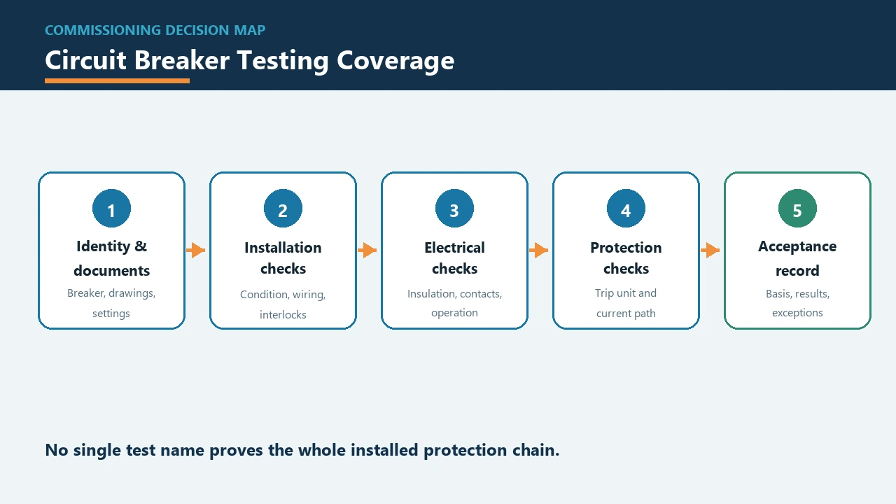
Acceptance comes from defined inspections and tests judged against the applicable breaker and project basis, rather than from the presence of one test set. The ANSI/NETA ATS overview frames acceptance testing as field inspection and testing used to assess suitability for initial energization.
That distinction matters when a completed panel is waiting for power. A sheet of readings may look complete, yet it cannot support a clear decision if no one can identify the breaker, the approved settings, the drawing revision, or the criterion used to judge each result.
An acceptance basis connects the observed result to the document that gives it meaning. Depending on the project, that basis can include the applicable standard, breaker instructions and tolerances, design specification, approved drawings, protection study, and setting record.
The decision path has three practical layers:
- Installed condition: the breaker, terminals, mechanism, grounding, control wiring, and interlocks match the intended assembly and show no unresolved condition that prevents testing.
- Functional and protection evidence: the chosen checks address the relevant insulation, current path, operating mechanism, sensing path, and trip-unit functions.
- Traceable disposition: results, exceptions, corrective work, retests, and sign-off are tied to the exact breaker and acceptance basis.
A tester therefore belongs inside a commissioning plan. It supplies evidence for a particular question; the plan determines whether all important questions have been answered before energization.
Lock the Breaker Identity, Documents, and Safety Controls First
Confirm the exact breaker, applicable documents, qualified personnel, and inspected, correctly rated test gear before making a test connection. Method selection is premature while the device identity or the acceptance basis remains uncertain.
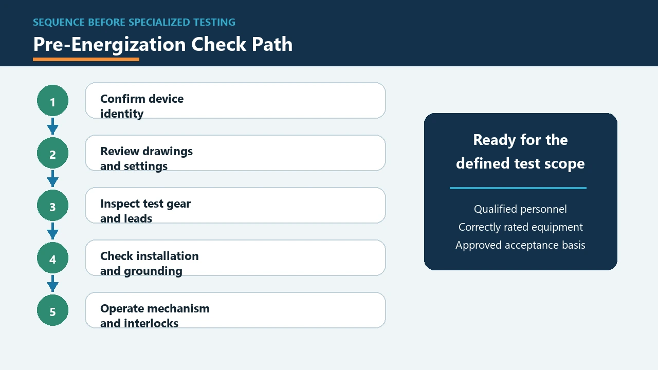
Nameplate information, model or family identity, panel location, and the approved drawing reference should point to the same installed device. For an electronic trip unit, the record also needs the approved setting information and the relevant device instructions before an injection method is selected.
The document check is especially important when similar breakers appear in one assembly. A result filed against a family name alone may later be impossible to connect to the correct feeder, settings, or serial identity.
| Prerequisite | Responsible input | Evidence before connection | Stop condition |
|---|---|---|---|
| Breaker identity | Panel builder or equipment supplier | Model/family, device identifier, panel location, nameplate record | Device cannot be matched to the drawing or test sheet |
| Approved documents | Design and project team | Current drawings, specification, settings, breaker instructions | Revision or setting basis is missing or inconsistent |
| Testing personnel | Commissioning organization | Assigned qualified personnel and defined responsibilities | Competence or responsibility is unresolved |
| Test instruments and leads | Commissioning organization | Instrument identification, condition check, and rating fit for the circuit/equipment | Damage, defect, or unsuitable rating is found |
| Test scope | Project and commissioning team | Named inspection or test method linked to an acceptance source | A generic test name has no defined coverage or criterion |
Important: In U.S. workplaces, OSHA 1910.334(c) assigns electrical testing work to qualified persons and requires visual inspection of test instruments and accessories before use. The same section requires instruments and accessories to be rated for the circuits and equipment to which they are connected.
For projects outside the U.S., follow the governing local and site safety rules. Regardless of jurisdiction, do not connect damaged, defective, or incorrectly rated test gear.
IEC 60947-2:2024 identifies a product-standard scope for circuit-breakers operated by instructed or skilled persons; it does not supply a project-specific field-test value in its public catalog description. Record the standard, device instructions, and project documents that actually govern the installed breaker.
Inspect the Installation, Mechanism, Wiring, Grounding, and Interlocks
Visual and mechanical checks establish that the breaker and its installed interfaces are ready for electrical testing. Specialized measurements cannot reveal every assembly, connection, grounding, alignment, or interlock problem.
Begin at the physical installation because later results can be misleading when the basic assembly condition is unknown. The inspection record should identify what was seen, what was operated, and which anomaly requires correction before the test sequence continues.
Useful inspection groups include:
- breaker identification, physical condition, cleanliness, mounting, and alignment;
- main and auxiliary connection condition against the approved assembly information;
- grounding or protective bonding condition at the relevant installed interfaces;
- manual opening, closing, charging, reset, and position indication where those functions apply;
- mechanical and electrical interlocks that are part of the installed design;
- control wiring, auxiliary circuits, and operating devices included in the commissioning scope.
Consider a breaker that opens and closes by hand while its control wiring or an interlock has not been checked. Manual operation is useful evidence about the mechanism, but it leaves a different installed function unanswered.
The same separation prevents an insulation reading from becoming a substitute for a physical inspection. Damage, loose installation details, or an unresolved interlock condition needs its own disposition even if an unrelated electrical value appears acceptable.
Match Each Electrical Check to the Condition It Reveals
Insulation resistance, contact resistance, timing, and coil or operating checks produce different evidence and should be selected for the condition being assessed. Treating them as interchangeable hides gaps in the commissioning scope.
Insulation resistance assesses insulation condition between specified conductive points under the chosen procedure. In plain language, it looks for an unwanted leakage path; it does not describe the resistance through closed main contacts or the trip unit’s response.
Contact resistance addresses the main contact or current-carrying path under the selected method. Breaker timing examines operating time and, where applicable, the relationship between pole operations, while coil or powered operating checks address the associated opening and closing functions included in the design.
| Check family | Area or condition observed | Evidence produced | Separate question still needing coverage |
|---|---|---|---|
| Visual and mechanical inspection | Installation, mechanism, connections, grounding, wiring, interlocks | Recorded condition and functional observations | Insulation, current-path resistance, and protection response |
| Insulation resistance | Insulation condition between specified points | Measured insulation result tied to a defined connection and procedure | Main-contact condition, operating time, and trip logic |
| Contact resistance | Main-contact or current-carrying path | Resistance result for the selected path and method | Insulation condition and trip-unit response |
| Breaker timing and operation | Mechanism operation and applicable pole relationship | Operating-time or functional record | Sensing accuracy and the primary current path |
| Coil or control operation | Opening, closing, or control function included in the design | Functional or measured operating evidence | Primary sensing and protection coverage |
| Protection or injection check | Selected portion of the sensing and trip chain | Response associated with the applied method | Any portion of the installed chain excluded by that method |
The result becomes useful when the report states the connection, method, instrument, breaker state, observed value, and acceptance source. A bare label such as “IR done” or “timing passed” leaves too much of the decision unstated.
Method selection should follow the device and project documents rather than a universal checklist. Test voltage, resistance limit, timing limit, and interval must come from the documents that govern the actual breaker and installation.
Readers who first need to distinguish MCCB, ACB, and other device classes can use the circuit breaker types guide without turning the commissioning record into another taxonomy exercise. Questions about trip causes and curve behavior belong in the separate circuit breaker trip guide.
Choose Injection Testing by the Protection Chain You Need to Exercise
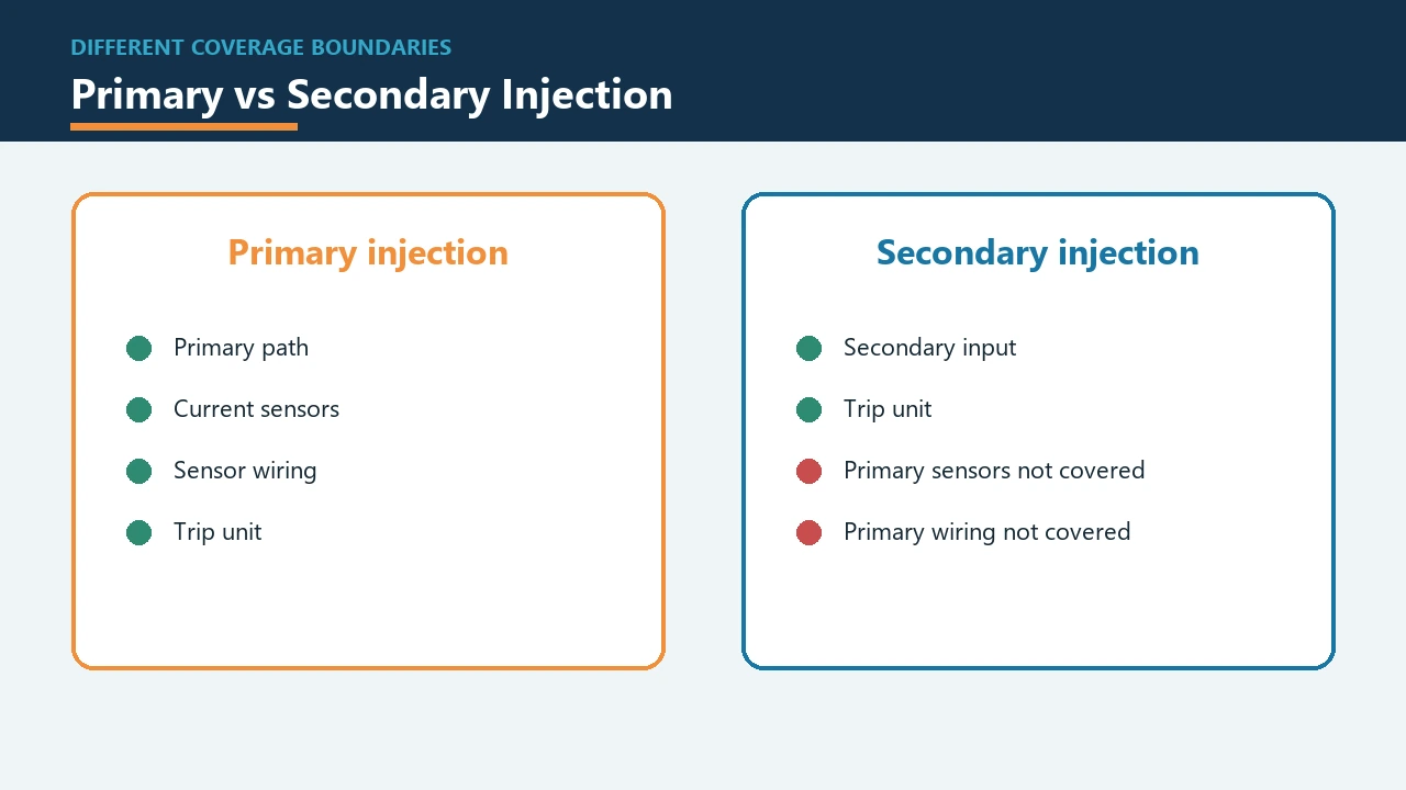
Primary injection includes more of the sensing and current path, while secondary injection focuses on trip-unit behavior and excludes the primary sensors and their wiring. The correct choice depends on which portion of the installed protection chain must participate in the test.
Primary injection applies test current through the primary path so the applicable current sensors, sensor wiring, current-carrying path, and trip unit take part. This broader path is valuable when the commissioning question concerns the installed sensing-and-trip chain rather than the trip unit alone.
Secondary injection applies a test input at the electronic trip unit. It can examine the trip unit’s protection logic and response while leaving the primary current sensors and their wiring outside the test path.
| Decision factor | Primary injection testing | Secondary injection testing |
|---|---|---|
| Test stimulus | Applied through the primary current path | Applied at the trip-unit test input or interface |
| Participating elements | Applicable current path, sensors, sensor wiring, and trip unit | Trip-unit logic and associated response under the selected mode |
| Useful commissioning question | Does the required installed sensing-and-trip chain respond through the primary path? | Does the trip unit respond to the defined secondary test input? |
| Coverage excluded from the method | Conditions outside the configured primary test and separate inspection/diagnostic needs | Primary sensors, their wiring, and the main current path |
| Scope input needed | Breaker arrangement, device instructions, settings, safe test setup, and required chain coverage | Compatible trip-unit method or interface, device instructions, settings, and required response |
A buyer who requests only an “injection test” has not yet defined the deliverable. The request should say whether the trip unit alone or the installed sensing and current path must be exercised, then identify the applicable response basis and report fields.
The method distinction is discussed in practical terms by the TestGuy Electrical Testing Network. Its explanation is useful for coverage, while the actual procedure still comes from the breaker, test equipment, project, and safety documents that apply to the job.
Turn Test Results into a Reviewable Acceptance Record
For a buyer-ready record, require every result to be tied to the breaker, method, instrument, governing acceptance source, anomaly status, corrective action, and responsible sign-off. Readings without those links are difficult to review and even harder to revisit after the panel enters service.
The record begins with device identity because every later line depends on it. It then names the acceptance basis, captures the procedure and instrument, preserves the observed result, and closes any exception through correction, retest, and disposition.
| Record field | What it should make clear | Why it matters at acceptance |
|---|---|---|
| Device identity | Breaker model/family, unique identifier, panel location, and relevant trip-unit identity | Prevents results from being filed against the wrong installed device |
| Document and setting basis | Approved drawing, breaker instruction, project specification, study, setting record, and applicable standard | Defines how the method and result are judged |
| Method and setup | Inspection or test name, connection or path, breaker state, and procedure reference | Shows which condition or chain segment participated |
| Instrument record | Instrument identifier, appropriate rating, condition check, and project-required status information | Links the reading to the equipment used to obtain it |
| Result and criterion | Observed result plus the named tolerance, requirement, or source used for the decision | Separates measurement from acceptance judgement |
| Exception and correction | Anomaly, responsible action, repair or adjustment, and retest result | Prevents an open issue from disappearing behind a summary status |
| Sign-off and disposition | Responsible reviewer, date, final status, and energization disposition | Creates a clear close-out decision |
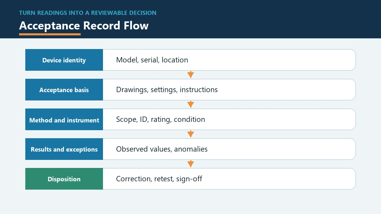
This structure also handles a failed or uncertain result more honestly than a single overall check mark. The anomaly remains visible until the corrective action and any required retest have a documented disposition.
When a result cannot be judged, the next action is to find the missing basis rather than invent a threshold. That may mean retrieving the correct device instruction, approved setting, protection study, design specification, or governing acceptance requirement.
Split Breaker Documents from Commissioning Test Deliverables
The RFQ should separate the breaker product-document package from the commissioning deliverable. On the product side, request the exact device identity and agreed published documents; on the commissioning side, define personnel, methods, instruments, results, acceptance basis, and close-out evidence. Keeping those deliverables separate prevents a data sheet from being mistaken for a completed field-test package.
Procurement needs both sides to meet at the device identity. The supplier information tells the commissioning party what breaker and trip unit are installed, while the project documents determine which inspections and test methods are required before energization.
| Deliverable group | Breaker/product side | Commissioning side |
|---|---|---|
| Device definition | Model or family, relevant options, nameplate information, and published instructions in the agreed supply scope | Match the installed identity to the panel location and test record |
| Design and settings | Available product documentation and identified trip-unit context | Approved drawings, protection study, project specification, and setting record |
| Test planning | Device information needed to select a compatible and relevant method | Qualified personnel, safe procedure, method coverage, instruments, and schedule |
| Acceptance evidence | Agreed supply documents or factory records when included | Field observations, measured results, anomalies, corrections, retests, and sign-off |
| Open questions | Clarification of the supplied breaker and current published documentation | Clarification of the test method, acceptance source, coverage, and close-out responsibility |
For electronic or intelligent breakers, procurement should identify the trip unit and obtain the applicable instructions before promising a secondary injection method. A generic assumption about a test interface or accessory can create a gap between the purchased breaker and the commissioning plan.
The IEC 60947-2:2024 catalog entry identifies the standard’s circuit-breaker scope, but it is not a substitute for the breaker instructions or project acceptance documents. The RFQ should name the standards and records that apply without copying a field-test value from a catalog description.
Post-replacement checks follow the same identity-and-evidence logic. The breaker replacement guide covers the separate replacement decision, while the commissioning package records the checks performed on the installed result.
Use SUTON Breaker Paths to Define the Device, Not the Test Set
ETM1 and ETM3E can anchor breaker identity and documentation discussions, but SUTON’s published product catalog does not list a circuit breaker tester or a field-test result. Use these paths to define the installed protective device before assigning the separate commissioning method.
The ETM1 molded-case circuit breaker provides a conventional MCCB family path for the product side of the record. Its model context can support device identification, while the project team still names the applicable instructions, settings, tests, and acceptance basis.
The ETM3E intelligent measurement circuit breaker provides an intelligent measurement and protection breaker path. That context makes trip-unit documentation and supported test-method questions especially relevant, but it does not establish an injection accessory or a completed field test.
The broader SUTON products index is the upward path for component selection. If current breaker documents are needed, the request should identify the intended family and project context rather than asking SUTON for tester hardware that is not listed in the published catalog.
FAQ
What tests are performed on circuit breakers?
The selected scope may include visual and mechanical inspection, insulation resistance, contact resistance, timing or operating checks, control or coil checks, and protection testing by primary or secondary injection. The actual combination follows the installed breaker, its instructions, the design specification, approved settings, protection study, and applicable acceptance requirements.
Is there a universal seven-test commissioning sequence?
No fixed sequence applies to every breaker and installation. Begin with identity, documents, safety controls, and physical readiness, then select electrical and protection checks that answer the conditions and chain coverage required by the applicable acceptance basis.
Who should perform circuit breaker testing?
Qualified commissioning personnel should perform the work under the safety rules that govern the site and test activity. For U.S. workplaces, OSHA 1910.334(c) specifically assigns testing on electrical circuits and equipment to qualified persons and addresses instrument inspection and ratings.
Does secondary injection test the current sensors and wiring?
No. In the method described by TestGuy, secondary injection exercises the solid-state trip unit while the primary current sensors and their wiring remain outside the tested path.
What is the purpose of primary injection testing?
Primary injection is used when the test needs the applicable primary current path, current sensors, sensor wiring, and trip unit to participate. It covers more of the installed sensing-and-trip chain than a trip-unit-only secondary injection check.
What should a circuit breaker test report include?
Include device and panel identity, applicable documents and settings, the method and breaker state, instrument identification, observed results, acceptance source, anomalies, corrective actions, retests, and responsible sign-off. Each result should remain traceable to the breaker and the condition or function it was intended to assess.
How should a buyer choose a test method when no universal pass value exists?
Start with the exact breaker and trip-unit instructions, the design specification, approved settings or protection study, and the governing acceptance requirements. Choose the inspection or test method that exercises the required part of the installed chain, then name the document or criterion that will be used to judge the result.
Does SUTON sell a circuit breaker tester?
SUTON’s published product catalog does not list a circuit breaker tester or injection test set. Its relevant paths here are breaker and component products such as ETM1 and ETM3E, which can supply device context for a separately defined commissioning scope.