


An earth leakage circuit breaker adds shock protection by detecting imbalance between live and neutral conductors. Contractors integrating ELCBs or RCDs into LV panels need documented IΔn, wiring topology, and coordination with upstream overcurrent devices—not a generic safety breaker line on the bill of materials. Align device choice with the single-line diagram and project standards (IEC or NEC where cited) without implying automatic code approval for any catalog SKU.
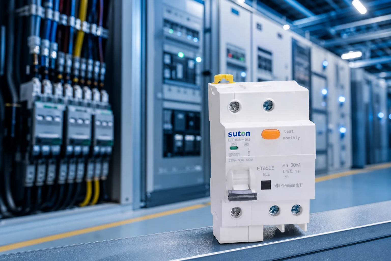
Part 1. What does an earth leakage circuit breaker do in LV panels?
ELCBs and RCDs interrupt a circuit when leakage current to earth exceeds a defined threshold (IΔn). They complement overcurrent protection rather than replacing it.
Shock protection versus overcurrent duty
An MCB may never trip on a person-contact fault that does not draw enough current to open the thermal or magnetic element. Residual-current devices address that gap by sensing imbalance between live and neutral conductors.
Treat ELCB/RCD selection as a documented engineering decision tied to the single-line diagram, not a generic add-on line copied from a previous project template.
Factory-installed versus field-added modules
IEC 61439 assemblies may integrate RCD modules as part of the verified switchgear system—reference assembly-level documentation when the ELCB is factory-installed rather than a field-added module.
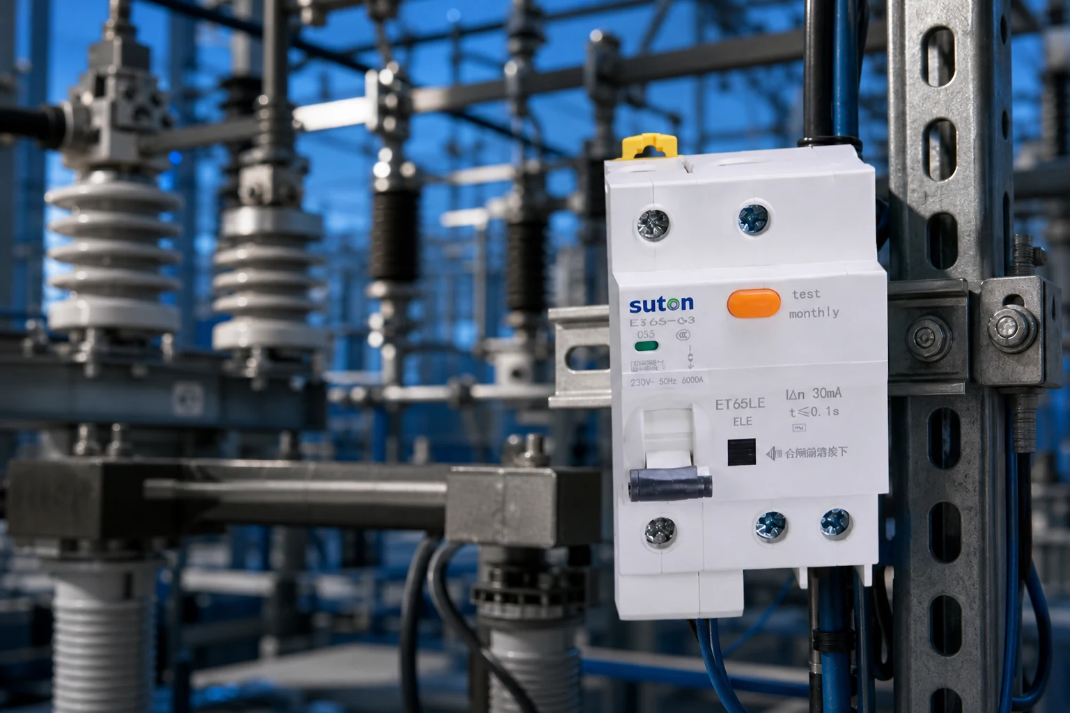
Part 2. How do ELCB, RCD, and RCBO names differ on export drawings?
Regional terminology differs even when the underlying protection function is similar. RFQ confusion often starts at naming—not at IΔn calculations.
Export ELCB and RCD labels
Earth leakage circuit breaker and residual current device appear frequently in export specifications. Both describe leakage sensing; the exact product standard and wiring topology still matter for acceptance tests.
RCBO and grouped RCD layouts
An RCBO combines leakage and overcurrent protection in one outgoing module. A grouped RCD upstream of several MCBs changes neutral routing, test-button access, and nuisance-trip sensitivity when electronic loads share the protected group.
GFCI and feeder protection references
Where project documents reference NEC Article 210.8 or equipment-level ground-fault protection on feeders, map the requested function to documented IΔn, time delay, and breaking capacity—cite the applicable code without implying automatic approval for any export SKU.
Export RFQs sometimes reuse labels from prior projects—verify the required function (leakage only, combined RCBO, or grouped RCD) against the consultant’s shock-protection schedule before copying a BOM line.
Part 3. Which ratings should contractors verify before quotation?
Record nominal voltage, system frequency (50 or 60 Hz as applicable), rated current, and short-circuit breaking capacity at the installation point before comparing quotations.
IΔn class and time delay
Specify IΔn (30 mA is common for personnel protection in many specifications), any time-delay class, and whether selective (S-type) coordination with upstream devices is required. Mixing 30 mA and 300 mA devices on the same protected group without engineering review is a frequent source of acceptance test failures.
Breaking capacity at panel terminals
Breaking capacity must clear prospective fault current on the feeder—not only load current. IEC 60947-2 defines test duties for circuit-breakers; cite Icu/Ics at system voltage from the fault study rather than relying on nominal ampacity alone.
Auxiliaries and enclosure environment
List shunt trip, auxiliary contacts, and lockable isolation when the operations team expects them. Enclosure IP, humidity, and corrosive atmospheres affect RCD electronics and test-button accessibility.
| Rating / data | Typical question it answers | Source |
|---|---|---|
| IΔn and time delay | Personnel vs equipment protection | Specification / consultant |
| Breaking capacity (kA) | Survives fault at panel terminals | Fault study |
| Wiring scheme | RCD grouping, neutral isolation | Single-line diagram |
| Enclosure / IP | Moisture and dust exposure | Site environmental class |
Part 4. Which wiring topologies fit commercial panels?
Place ELCB/RCD stages where the single-line diagram shows them—typically ahead of final circuits that require shock protection, or as RCBOs on individual outgoing ways.
RCBO on each outgoing way
Per-way RCBOs simplify circuit identification and reduce shared-neutral loading effects, but consume more physical ways and busbar ampacity than grouped solutions.
Grouped RCD feeding multiple MCBs
Grouped RCDs economize module count but concentrate nuisance-trip risk when VFDs, UPS feeders, or filter ground paths share the protected neutral. Avoid unapproved mixing of protective earth and neutral paths that can defeat the sensor.
Standalone RCD modules in IEC assemblies
Factory-assembled IEC boards may use dedicated RCD modules verified with the assembly type test. Field substitutions should stay within the verified device list when type test summaries are part of the contract.
Cable entry and neutral bar layout determine whether grouped RCDs remain serviceable after installation. Review test-button reachability when the enclosure door is closed and latched.
Part 5. How should ELCBs coordinate with upstream overcurrent devices?
Leakage protection clears high-impedance earth faults; short-circuit duty remains with devices rated for prospective fault current at the panel terminals.
Selective RCD and upstream MCCB
Selective coordination between upstream MCCB and downstream RCBO/ELCB may require time-current review when generators or UPS feeds are present. IEEE 141 emphasizes documenting which device clears which fault type.
Short-circuit rating versus IΔn sensitivity
A device sized only for leakage sensitivity but not for bolted fault duty is a common retrofit liability. Compare manufacturer data at the stated prospective fault current—not amp rating alone.
Part 6. What causes nuisance tripping and test-access gaps?
Nuisance tripping on mixed electronic loads often traces to filter ground paths or shared neutral loading—not a defective device.
Electronic load leakage paths
When nuisance tripping appears on VFD or UPS feeders, review leakage sensitivity and wiring before downgrading IΔn without engineering approval.
Labeling and maintenance isolation
Label each protected circuit clearly. Maintenance crews lock out upstream devices before work; ambiguous RCD group labels slow isolation during outages.
Bonding is not optional
Residual-current protection does not remove the need for proper grounding and bonding on the installation—document bonding layout alongside RCD datasheets.
Seasonal humidity swings can shift leakage readings on outdoor assemblies. Document environmental class on the quotation so IΔn and enclosure ratings stay aligned through acceptance testing.
Part 7. Which IEC standards and RFQ handover items apply?
IEC 60947-2 covers circuit-breaker tests; assembly rules often reference IEC 61439. Handover documents should ship together with device datasheets.
IEC 60947-2 and device verification
Request Icu/Ics values at the system voltage assumed on the single-line diagram. Type test excerpts at device level support export acceptance when assembly-level summaries are not yet available.
Commissioning and circuit charts
Handover should include wiring diagrams showing neutral routing, IΔn settings, test-button locations, and any selective RCD type markings required by the specification. Export panels should ship with circuit charts even when final inspection occurs abroad.
When the owner references both IEC 61439 assembly rules and device-level IEC 60947-2 certificates, list which document covers the installed module versus the complete board to avoid duplicate or missing evidence at customs review.
| RFQ / handover item | Purpose | When to include |
|---|---|---|
| IΔn and breaking-capacity datasheet | Proves shock and fault duty | Before purchase order |
| Wiring diagram (neutral routing) | Assembly and test-button access | Design phase |
| Type test excerpt (device level) | Supports export acceptance | Technical review |
| Commissioning test record | Documents trip-button verification | Before energization |
Part 8. Which molded-case RCBO ranges fit typical panel integration?
Once IΔn, wiring topology, and fault level are fixed on the approved diagram, RCBO selection narrows to molded-case ranges that match your panel platform and export documentation package—not generic safety breaker labels alone.
ETM1L for integrated moulded-case RCBO ways
The ETM1L series suits specifications that call for combined overcurrent and residual-current protection in a molded-case frame. Compare IΔn class, breaking capacity, and auxiliary options against the fault study before freezing the bill of materials.
ETM3EL for electronic residual-current protection
The ETM3EL series addresses projects that require electronic residual-current detection with adjustable sensitivity features. Pair device curves with upstream MCCB data when selective coordination is contractual.
When to involve factory engineering
Share the single-line diagram, IΔn requirements, and any grouped-RCD versus per-way RCBO decision before formal quotation. Factory engineering can align module cutouts, neutral bars, and export test records with your panel BOM.
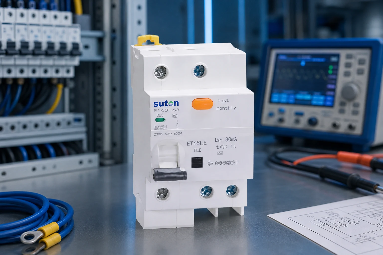
When your single-line diagram and load schedule are fixed, compare SUTON ETM1L Series RCBO and SUTON ETM3EL Series RCBO, explore application solutions, or review OEM/ODM capabilities. For datasheet alignment against your fault study, SUTON engineering support can review project parameters.
FAQ
What is an earth leakage circuit breaker used for?
It detects leakage current to earth and interrupts the circuit to reduce electric shock risk. It works alongside overcurrent devices such as MCBs or MCCBs rather than replacing them.
How do you select an earth leakage circuit breaker for a commercial panel?
Match IΔn, time-delay class, breaking capacity, and wiring topology to the single-line diagram and fault study. Confirm whether RCBO, standalone RCD, or grouped RCD protection is required.
What standards apply to earth leakage circuit breakers in LV assemblies?
IEC 60947-2 covers circuit-breaker tests; assembly rules often reference IEC 61439. U.S. projects also follow NFPA 70 (NEC) and local AHJ requirements.
How does an earth leakage circuit breaker coordinate with upstream breakers?
Leakage protection clears high-impedance earth faults; short-circuit duty remains with devices rated for prospective fault current. Selective RCD types may be required when upstream devices must remain closed.
What is the difference between an ELCB, RCD, and RCBO?
ELCB/RCD senses leakage; RCBO combines leakage and overcurrent in one module. Specifications should name the required function instead of using generic labels.
What documents should contractors request for earth leakage circuit breakers?
Request IΔn and breaking-capacity datasheets, wiring diagrams showing neutral routing, type test excerpts, and commissioning steps for the test button.
References