

Product Overview
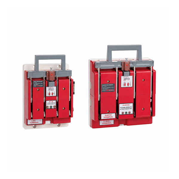
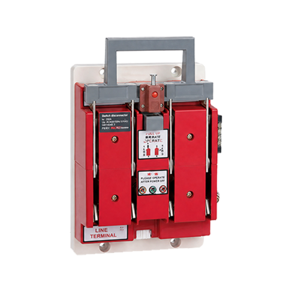
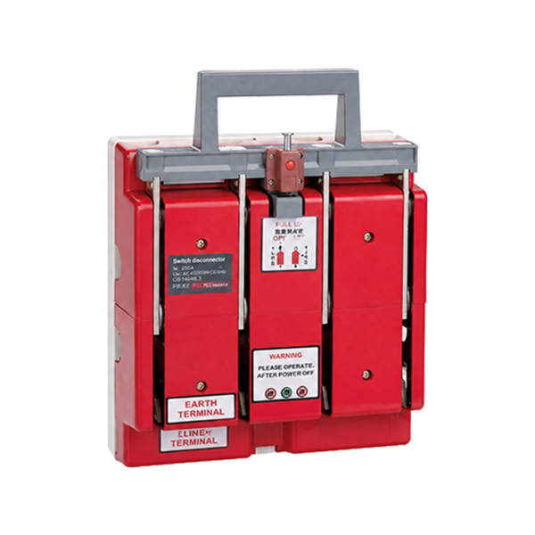
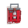
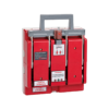
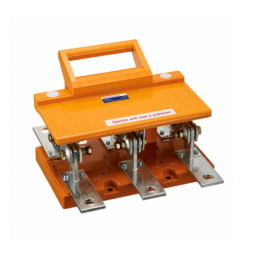
The HS11FD series switches were originally knife-type changeover switches and have been redesigned and improved into anti-misoperation isolators with earthing function (hereinafter referred to as “switches”). They are newly equipped with a mechanical interlocking mechanism, opening/closing signal output, earthing function, and live indication function. These features effectively solve the technical problems of difficult earthing of low-voltage switches, the risk of closing onto live lines, and the high likelihood of safety accidents. The switch features a simple structure and convenient earthing, which can prevent accidents caused by closing onto live lines and prevent accidents caused by load breaking with the knife switch. The switch is designed with two states: energized state and earthing state. This switch complies with the requirements of GB/T 14048.3-2008.
Normal Service and Installation Conditions
■Ambient air temperature not higher than +40℃ and not lower than -5℃ .
■Installation altitude not exceeding 2000 m.
■Humidity: At a maximum temperature of +40℃ , the relative humidity of the air shall not exceed 50%. Higher relative humidity is permitted at lower temperatures (e.g., 90% at 20℃ ). Appropriate measures shall be taken against occasional condensation caused by temperature variations.
■Pollution degree of the surrounding environment is degree 3.
■The switch shall be installed in a location free from significant vibration, shock vibration and rain/snow exposure. The installation site shall be free from explosive media, and the medium shall contain no gases or dust sufficient to corrode metal or damage insulation.
Main Technical Parameters
| Conventional free-air thermal current (A) | 200 | 400 | 600 |
| Rated insulation voltage (V) | 1000 | 1000 | 1000 |
| Rated operational voltage (V) | 400 | 400 | 400 |
| Mechanical endurance (operations) | 1600 | 1000 | 1000 |
| Rated short-time withstand current (kA) | 10 | 20 | 25 |
| Operating force (N) | ≤ 300 | ≤ 400 | ≤ 400 |
Ordering Instructions
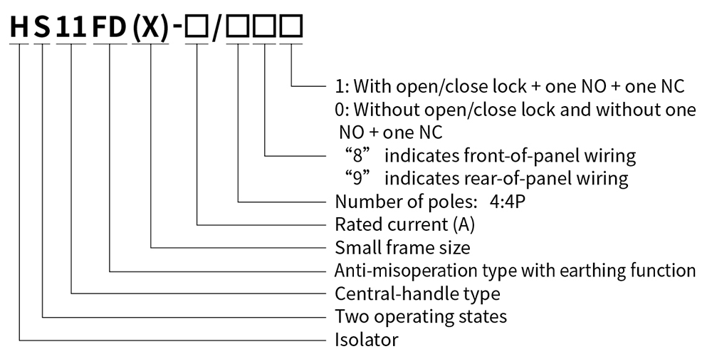
Due to the addition of the live indication function, the internal circuit has phase sequence requirements for power take-off. When ordering, please specify whether the neutral (N pole) is on the left or right side, and also indicate the current rating, wiring method, quantity, etc. For special orders, please consult our technical department. Example: HS11FD-200/48, N pole on left/right side, 10 units.
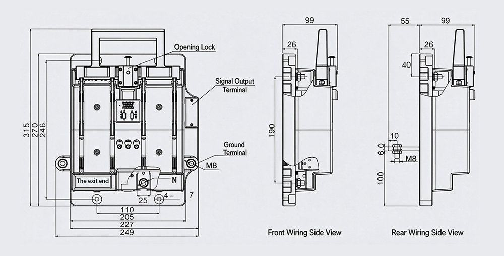
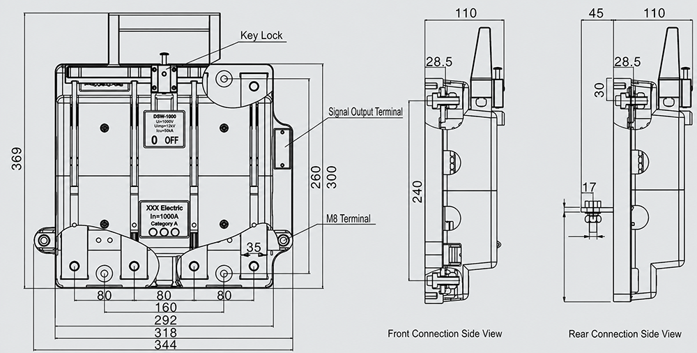
Outline and Mounting Dimensions (mm)
HS11FD-200
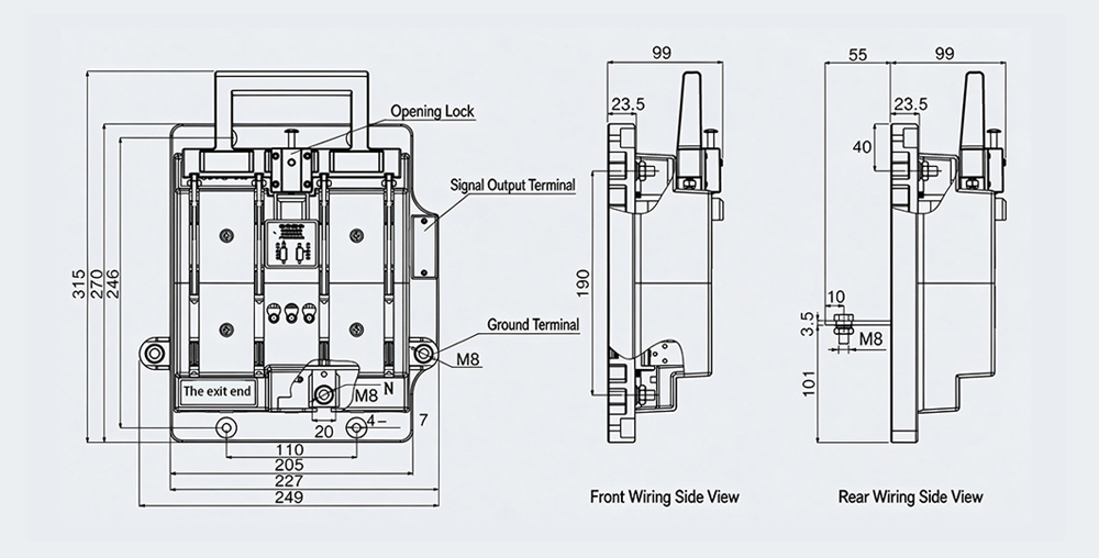
HS11FD(X)-400
HS11FD-600
Reviews
There are no reviews yet.