

Structural Features
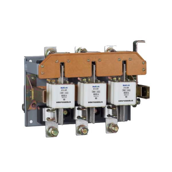
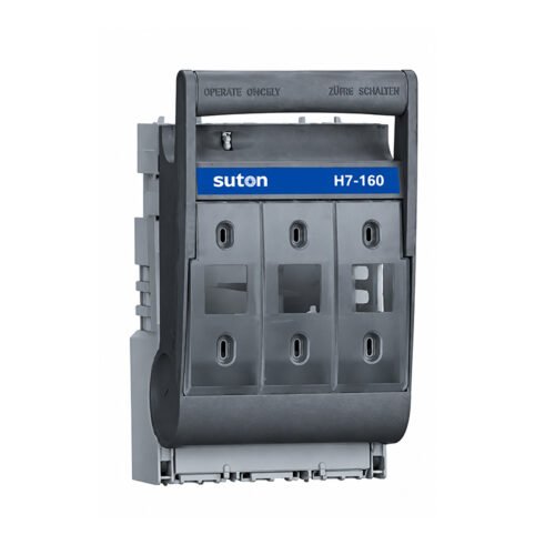
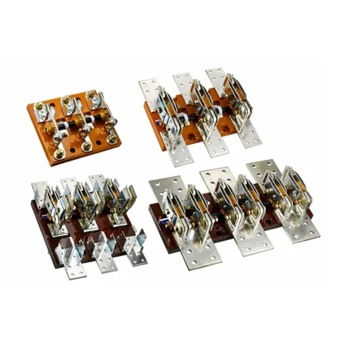
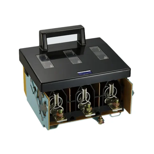
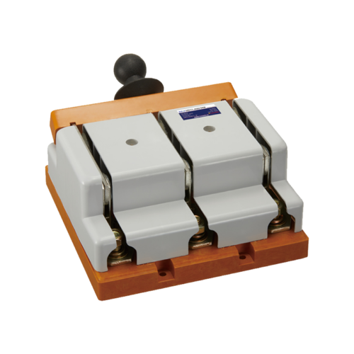
The fuse-switch disconnector (hereinafter referred to as “switch”) is a combination appliance of a fuse and a knife switch, possessing the basic performance of both the fuse and the knife switch. Under normal power supply conditions of the circuit, making and breaking of the power supply is performed by the knife switch. When the line or electrical equipment is overloaded or short-circuited, the fuse element melts and promptly interrupts the fault current. For front-operated front-access switches, there is a door in the center for inspection and replacement of fuses, mainly for installation on BDL distribution boards. Front-operated rear-access switches are mainly for installation on BSL distribution boards. Side-operated front-access switches can be made into enclosed power distribution boxes.
Knife switches with rated current of 600 A and below are equipped with safety barriers and arc chutes. The arc chute is formed by riveting phenolic laminated board and steel plate stamped parts.
The fuse of the switch is fixed on an insulating crossbeam with a spring and locking plate. During normal operation, the fuse is prevented from tripping. When the fuse element melts due to a line fault, the fuse can be easily replaced simply by pressing the locking plate.
Normal Service and Installation Conditions
- Ambient air temperature not higher than +40°C and not lower than -5°C.
- Installation altitude not exceeding 2000 m.
- Humidity: At a maximum temperature of +40°C, the relative humidity of the air shall not exceed 50%. Higher relative humidity is permitted at lower temperatures (e.g., 90% at 20°C). Appropriate measures shall be taken against occasional condensation caused by temperature variations.
- Pollution degree of the surrounding environment is degree 3.
- The switch shall be installed in a location free from significant vibration, shock vibration and rain/snow exposure. The installation site shall be free from explosive media, and the medium shall contain no gases or dust sufficient to corrode metal or damage insulation.
Scope of Application
The HR3 series fuse-switch disconnectors are suitable for use in AC 50 Hz, 400 V distribution systems with rated current up to 600 A for short-circuit protection and overload protection of wires and cables. Under normal conditions, they can be used for infrequent manual making and breaking of normal load current and overload current. Under short-circuit conditions, the current is interrupted by the fuse.
Main Technical Parameters
| Model | Rated operational voltage Ue (V) | Rated insulation voltage Ui (V) | Conventional free-air thermal current Ith (A) | Rated operational current Ie (A) | Fuse model |
| HR3-200 | 400 | 690 | 200 | 200 | RT0-200 |
| HR3-400 | 400 | 690 | 400 | 400 | RT0-400 |
| HR3-600 | 400 | 690 | 600 | 600 | RT0-600 |
| 200A | 400A | 600A | |
| Conventional free-air thermal current (A) | 200 | 400 | 600 |
| Rated operational current (A) | 200 | 400 | 600 |
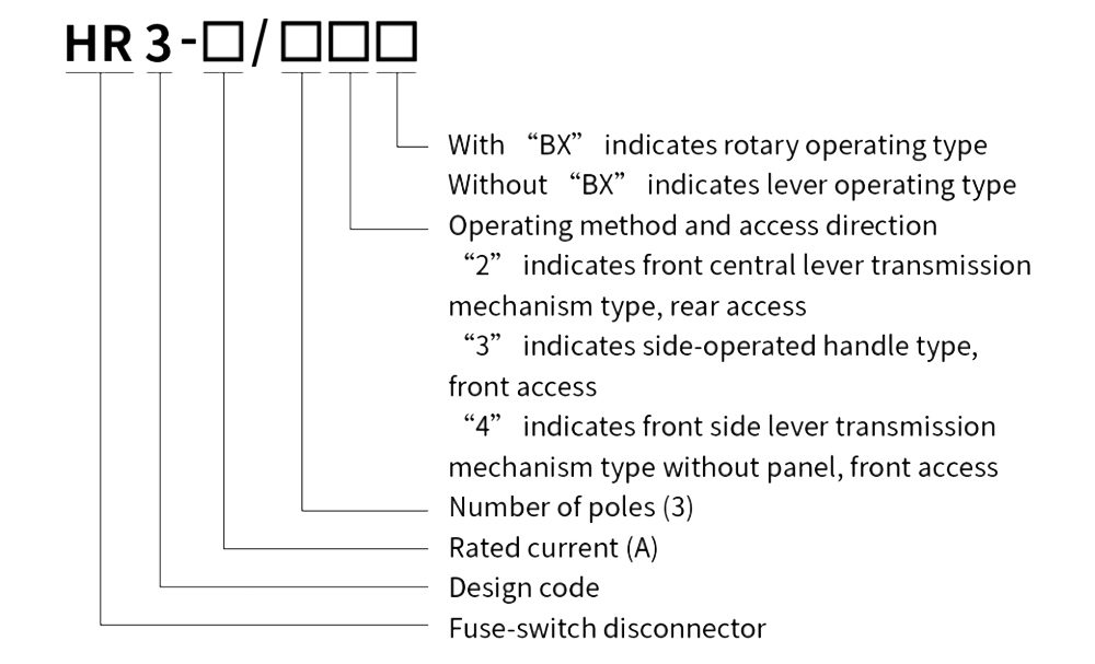
| HR3 front central lever transmission mechanism type HR3 |
HR3-200/32 | HR3-400/32 | HR3-600/32 |
| HR3 side-operated handle type HR3 |
HR3-200/33 | HR3-400/33 | HR3-600/33 |
| HR3 front side lever transmission mechanism type without panel HR3 |
HR3-200/34 | HR3-400/34 | HR3-600/34 |
Outline and Mounting Dimensions (mm)
HR3/32 Series (Without “BX” Type)

HR3/32 Series (With “BX” Type)

| Model | A | B | C | D | E | H | J | R | M | Φ |
| HR3-200 | 270 | 170 | 230 | 130 | 70 | 193 | 176 | 180 | 10 | 7 |
| HR3-400 | 290 | 170 | 250 | 130 | 80 | 194 | 194 | 180 | 12 | 7 |
| HR3-600 | 320 | 180 | 280 | 130 | 90 | 213 | 218 | 180 | 16 | 7 |
HR3/33 Series
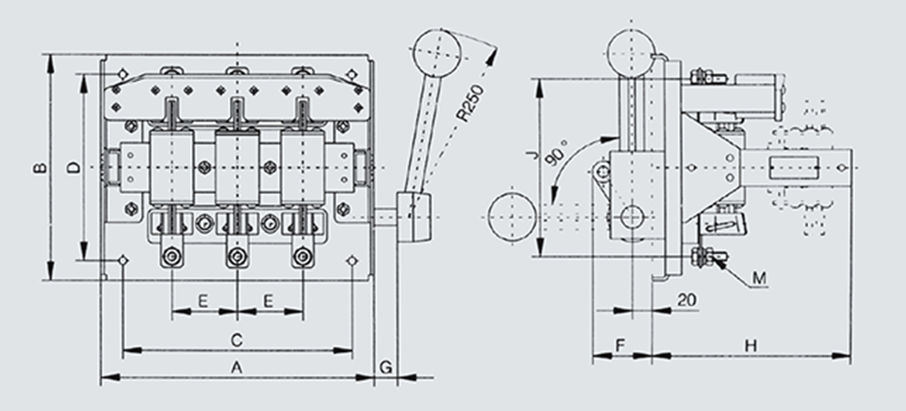
Drawing dimension labels: B, D, E, C, A, G, R250, 90°, M, 20, F, H
| Model | A | B | C | D | E | F | G | H | J | M | Φ |
| HR3-200 | 270 | 205 | 230 | 170 | 70 | 77 | 60 | 193 | 176 | 10 | 7 |
| HR3-400 | 290 | 290 | 250 | 170 | 80 | 77 | 55 | 194 | 194 | 12 | 7 |
| HR3-600 | 320 | 320 | 280 | 170 | 90 | 94 | 50 | 214 | 218 | 16 | 7 |
Note: Dimension F’ is the size when the handle is opened 90° and the connecting rod is at its maximum position.
HR3/34 Series
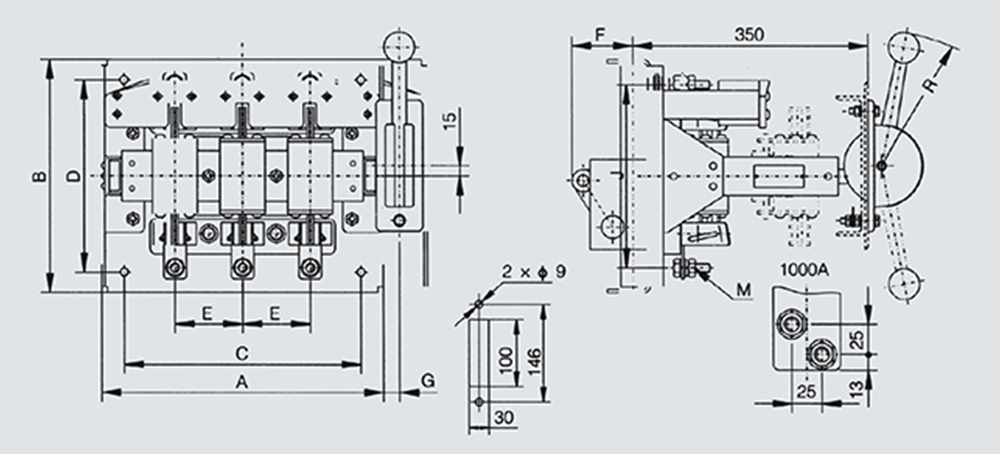
| Model | A | B | C | D | E | F | G | H | J | M | Φ |
| HR3-200 | 270 | 205 | 230 | 170 | 70 | 77 | 60 | 193 | 176 | 10 | 7 |
| HR3-400 | 290 | 290 | 250 | 170 | 80 | 77 | 55 | 194 | 194 | 12 | 7 |
| HR3-600 | 320 | 320 | 280 | 170 | 90 | 94 | 50 | 214 | 218 | 16 | 7 |
Note: Dimension F’ is the size when the handle is opened 90° and the connecting rod is at its maximum position.
HR3/34 Series — Ordering Information
When placing an order, the customer must specify the switch type characteristics, voltage rating, number of poles, operating method, quantity, etc. For special orders, please consult our company’s technical department.
Example: HR3-200/32 400 V, fuse current 100 A, 10 units
Reviews
There are no reviews yet.