

Product Overview
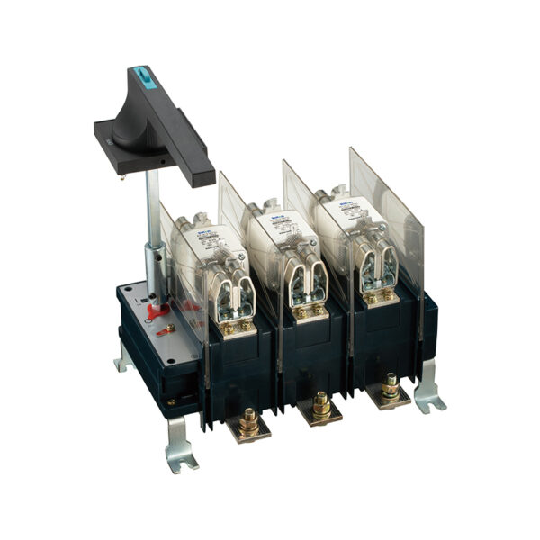
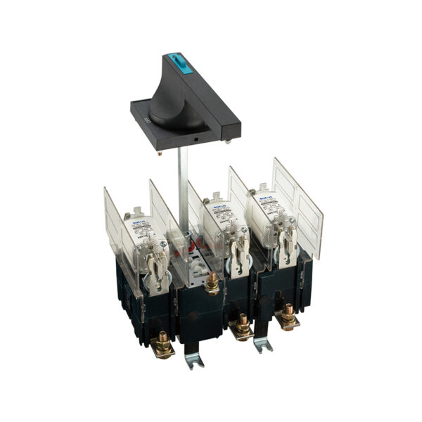
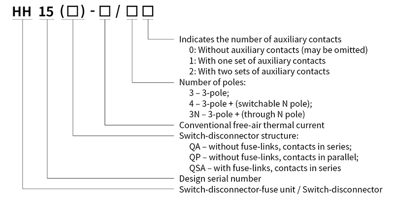
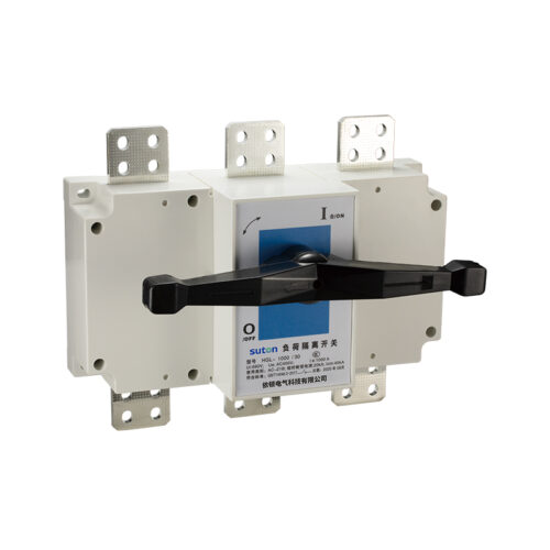
The HH15 series switch-disconnector-fuse units and switch-disconnectors (hereinafter referred to as “switches”) include the QSA series, QA series and QP series. They are mainly suitable for distribution circuits and motor circuits with high short-circuit currents, serving as manually operated main switches or master switches for infrequent operation. The QSA series switches can also be used for circuit short-circuit protection.
The switches comply with GB/T 14048.3 and IEC 60947-3 standards and are widely used in higher-pole drawer-type low-voltage complete sets of equipment.
Structural Features
- The switch adopts a front rotary operating mode and consists of an operating mechanism, contact system, handle, etc.
- The switch adopts a fully enclosed structure with spring energy-storage operation. The making and breaking speed of the switch is independent of the operator’s action speed, thereby ensuring the safety of personnel and equipment.
- The switch features a unique contact system. The moving contact system is directly formed by stacked copper sheets. The moving contact blades adopt a bridge-type structure with automatic adjustment function, ensuring effective line contact with the fixed contacts and thereby guaranteeing the stability of the product’ s temperature rise.
- The operating handle can be installed on the switchgear door. When the door is closed, the handle engages with the operating shaft of the switch. When the switch is in the closed position, the handle interlocks with the door to prevent the door from being opened.
- The switch is also equipped with an extension shaft; special lengths can be customized separately.
Normal Service and Installation Conditions
- Ambient air temperature not higher than +40 °C and not lower than -5 °C; the average temperature over a 24-hour period shall not exceed +35°C.
- Installation altitude not exceeding 2000 m.
- At an ambient air temperature of +40 °C, the relative humidity shall not exceed 50%. Higher relative humidity is permitted at lower temperatures (e.g., 90% at 20 °C). Special measures shall be taken against occasional condensation caused by temperature variations.
- Pollution degree of the surrounding environment is degree 3.
- The switch shall be installed in a location free from significant vibration, shock vibration and rain/snow exposure. The installation site shall be free from explosive media, and the medium shall contain no gases or dust sufficient to corrode metal or damage insulation.
Main Technical Parameters
HH15(QSA)-□/□□
| Model | Model | QSA-125 | QSA-160 | QSA-250 | QSA-400 | QSA-630 | QSA-800 | QSA-1250 |
| Number of main poles | Number of main poles | 3、3N、4 | 3、3N、4 | 3、3N、4 | 3、3N、4 | 3、3N、4 | 3、3N、4 | 3、3N、4 |
| Rated insulation voltage Ui | V | 690 | 690 | 690 | 690 | 690 | 1000 | 1000 |
| Rated impulse withstand voltage Uimp | kV | 8 | 8 | 8 | 8 | 8 | 12 | 12 |
| Rated operational voltage Ue | V | AC 400 | AC 400 | AC 400 | AC 400 | AC 400 | AC 400 | AC400 |
| Conventional free-air thermal current | A | 125 | 160 | 250 | 400 | 630 | 800 | 1250 |
| Rated operational current 400V:AC-22B | A | 125 | 160 | 250 | 400 | 630 | 800 | 1250 |
| Rated conditional short-circuit current at 400V | kA | 50 | 50 | 50 | 50 | 50 | 50 | 100 |
| Mechanical endurance (operations) | operations | 10000 | 10000 | 10000 | 10000 | 3000 | 3000 | 500 |
| Electrical endurance | operations | 500 | 300 | 300 | 300 | 200 | 200 | 100 |
| Fuse rated current at 400 V | A | 125 | 160 | 250 | 400 | 630 | 800 | 1250、1000、800 |
| Fuse size | 0 | 0 | 1 | 2 | 3 | 3 | 4 | |
| Operating torque | Nm | 7.5 | 16 | 16 | 16 | 30 | 30 | 38 |
| Auxiliary contact conventional free-air thermal current Ith, 400 V, AC-15A | A | 4 | 4 | 4 | 4 | 4 | 4 | 4 |
HH15(QA)-□/□□
| Model | Model | HH15-125 | HH15-160 | HH15-250 | HH15-400 | HH15-630 | HH15-1000 | HH15-1250 | HH15-1600 |
| Number of main poles | Number of main poles | 3、3N、4 | 3、3N、4 | 3、3N、4 | 3、3N、4 | 3、3N、4 | 3、3N、4 | 3、3N、4 | 3、3N、4 |
| Rated insulation voltage Ui | V | 690 | 690 | 690 | 690 | 690 | 1000 | 1000 | 1000 |
| Rated impulse withstand voltage Uimp | kV | 8 | 8 | 8 | 8 | 8 | 12 | 12 | 12 |
| Rated operational voltage Ue | V | AC 380 | AC 380 | AC 380 | AC 380 | AC 380 | AC 380 | AC 380 | AC 380 |
| Conventional free-air thermal current | A | 125 | 160 | 250 | 400 | 630 | 1000 | 1250 | 1250 |
| Rated operational current 380 V AC-21B | A | 125 | 160 | 250 | 400 | 630 | 1000 | 1250 | 1250 |
| Rated short-time withstand current Icw | kA/1s | 5 | 5 | 5 | 12.6 | 12.6 | 50 | 50 | 50 |
| Mechanical endurance | operations | 10000 | 10000 | 10000 | 10000 | 10000 | 3000 | 500 | 500 |
| Electrical endurance | operations | 500 | 500 | 300 | 300 | 300 | 200 | 100 | 100 |
| Operating torque | Nm | 7.5 | 7.5 | 16 | 16 | 16 | 30 | 38 | 38 |
| Auxiliary contact conventional free-air thermal current Ith 400 V, AC-15A | A | 4 | 4 | 4 | 4 | 4 | 4 | 4 | 4 |
HH15(QP)-□/□□
| Model | Model | HH15-250 | HH15-400 | HH15-630 | HH15-1000 | HH15-1250 | HH15-1600 | HH15-2500 |
| Number of main poles | Number of main poles | 3、3N、4 | 3、3N、4 | 3、3N、4 | 3、3N、4 | 3、3N、4 | 3、3N、4 | 3、3N、4 |
| Rated insulation voltage Ui | V | 690 | 690 | 690 | 1000 | 1000 | 1000 | 1000 |
| Rated impulse withstand voltage Uimp | kV | 8 | 8 | 8 | 12 | 12 | 12 | 12 |
| Rated operational voltage Ue | V | AC 380 | AC 380 | AC 380 | AC 380 | AC 380 | AC 380 | AC 380 |
| Conventional free-air thermal current | A | 250 | 400 | 630 | 1000 | 1250 | 1600 | 2500 |
| Rated operational current 380 V AC-21B | A | 250 | 400 | 630 | 1000 | 1250 | 1600 | 2500 |
| Rated short-time withstand current Icw | kA/1s | 5 | 12.6 | 12.6 | 50 | 50 | 50 | 50 |
| Mechanical endurance | operations | 10000 | 10000 | 10000 | 10000 | 3000 | 3000 | 500 |
| Electrical endurance | operations | 500 | 300 | 300 | 300 | 200 | 200 | 100 |
| Operating torque | Nm | 7.5 | 16 | 16 | 16 | 30 | 30 | 38 |
| Auxiliary contact conventional free-air thermal current Ith 400 V, AC-15A | A | 4 | 4 | 4 | 4 | 4 | 4 | 4 |
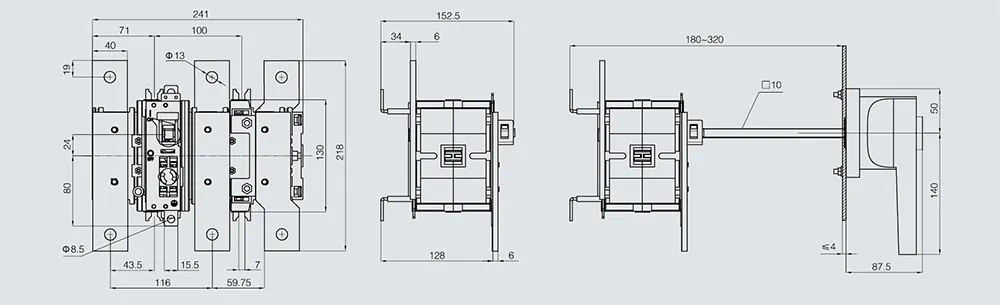
HH15(QSA)-125/3
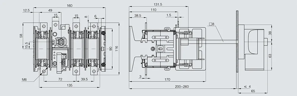
HH15(QSA)-125/3N HH15(QSA)-125/4
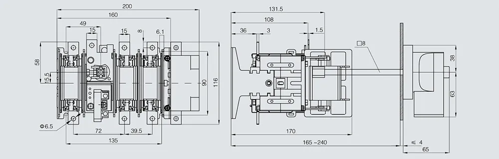
HH15(QSA)-160/3
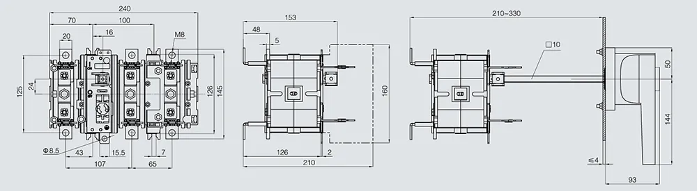
HH15(QSA)-250/3
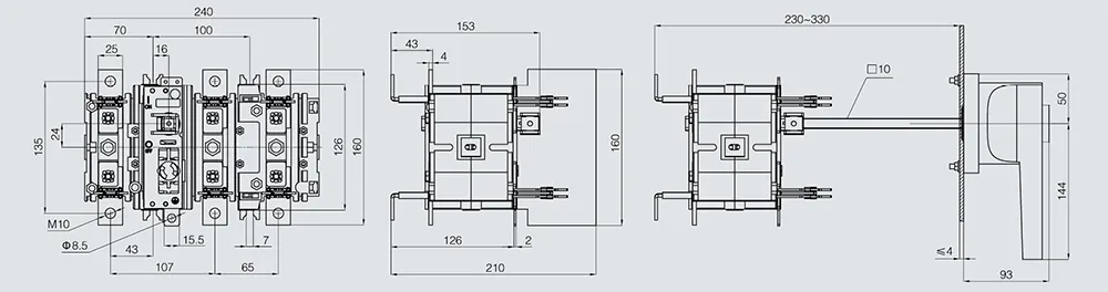
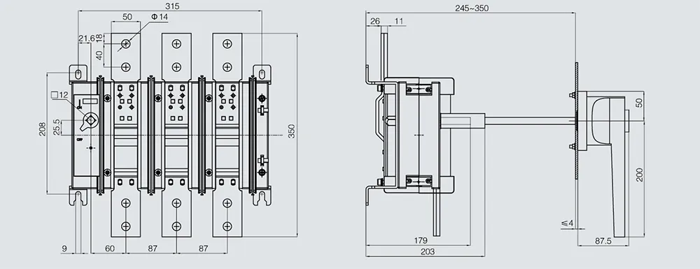
HH15(QSA)-400/3
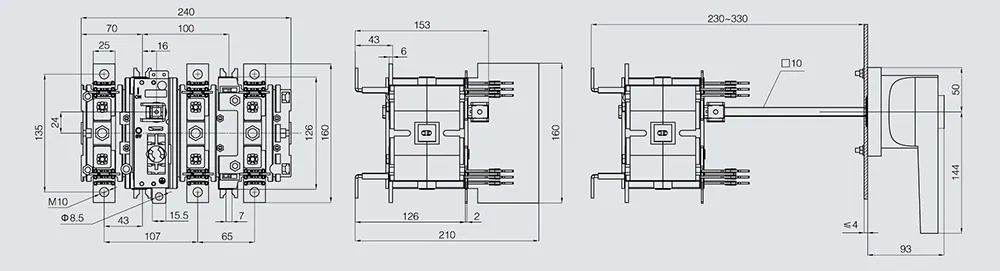
HH15(QSA)-400/3N HH15(QSA)-400/4
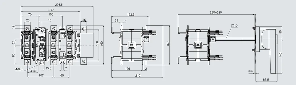
HH15(QSA)-630/3
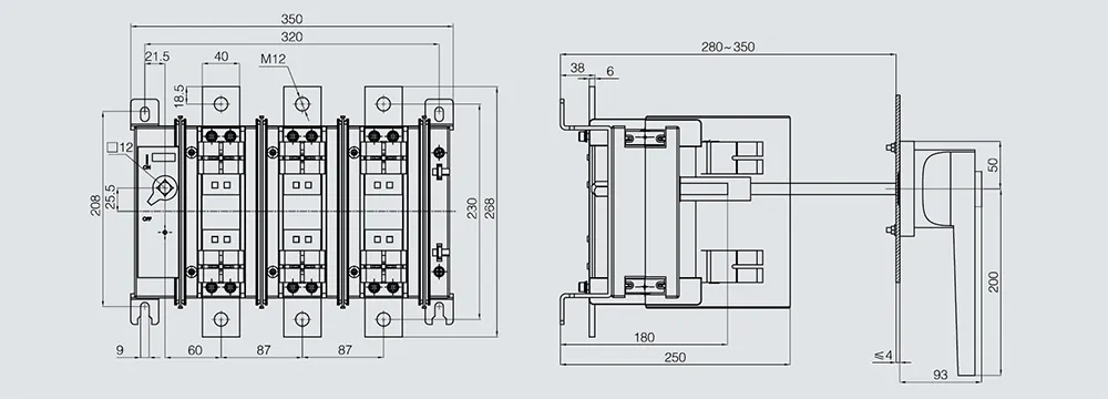
HH15(QSA)-630/3N HH15(QSA)-630/4
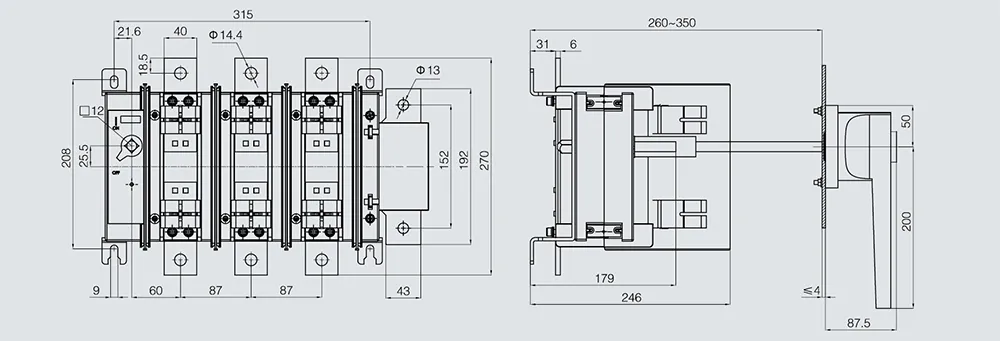
HH15(QSA)-800/3
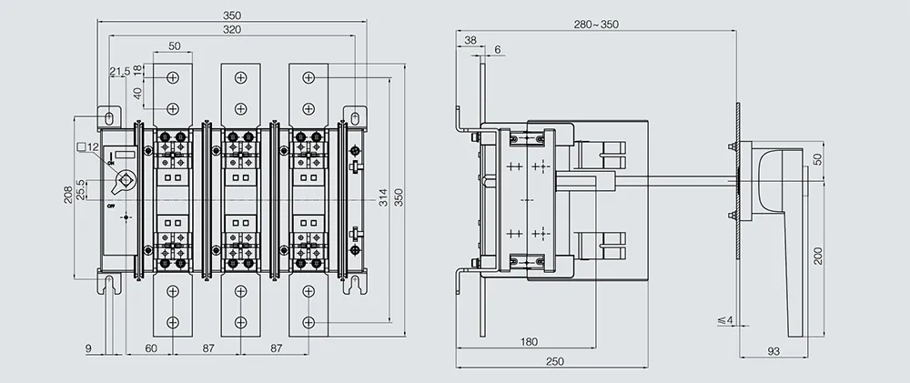
HH15(QSA)-800/3N HH15(QSA)-800/4
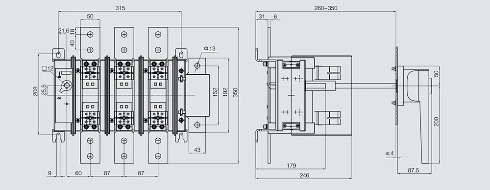
HH15(QSA)-1250/3
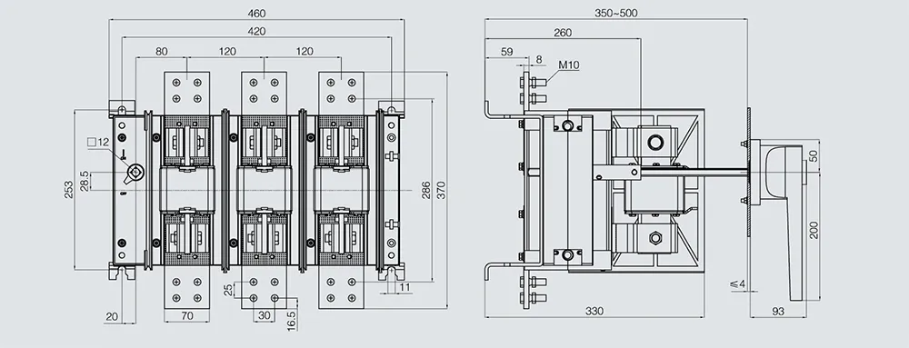
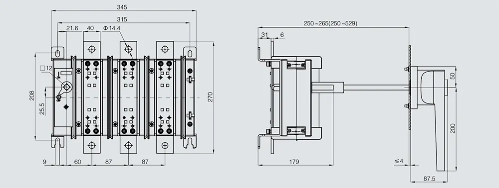
HH15(QA)-125/3
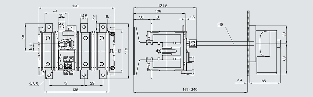
HH15(QA)-160/3 HH15(QA)-200/3
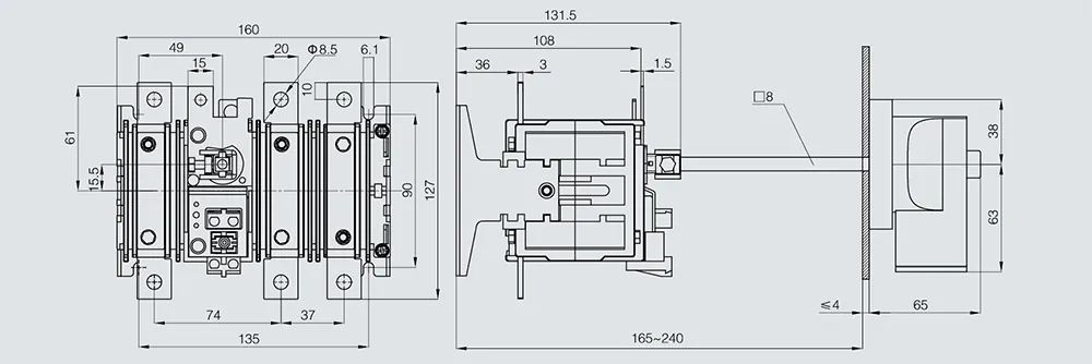
HH15(QA)-400/3
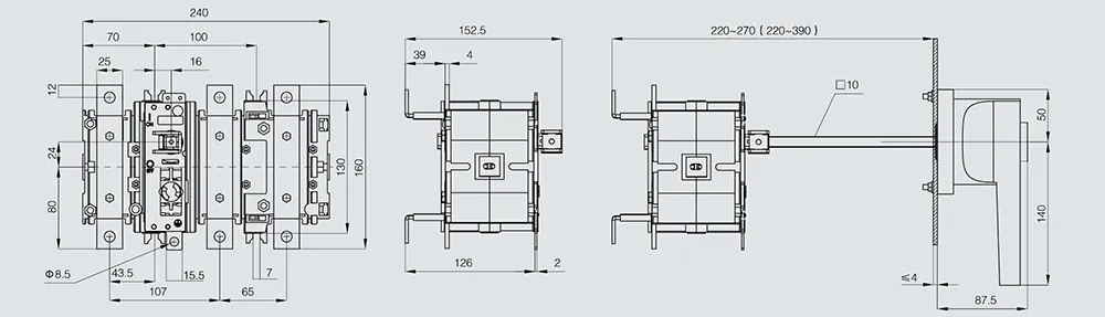
HH15(QA)-630/3
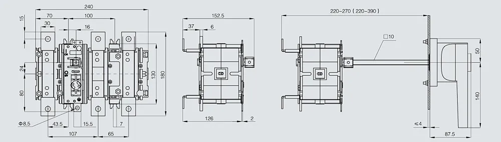
HH15(QA)-1000/3
HH15(QA)-1250/3 HH15(QA)-1600/3
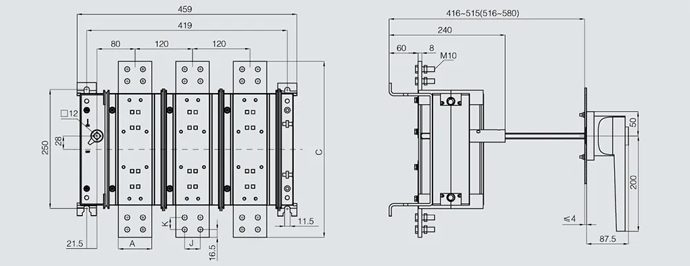
| Dimension | QA-1250 | QA-1600 |
| A | 70 | 80 |
| C | 370 | 380 |
| K | 25 | 30 |
| J | 30 | 40 |
Mounting Dimensions of HH15(QP) Series Switch-Disconnectors
HH15(QP)-250/3
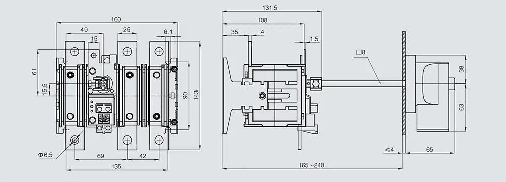
HH15(QP)-400/3 HH15(QP)-630/3
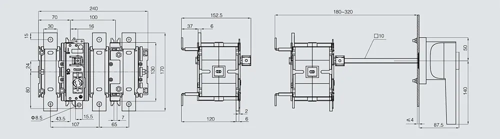
HH15(QP)-1000/3
HH15(QP)-1250/3 HH15(QP)-1600/3
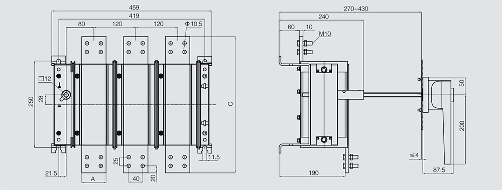
| QP-2000 | QP-2500 | |
| A | 70 | 80 |
HH15(QP)-2000/3 HH15(QP)-2500/3
Panel Cut-out Dimensions
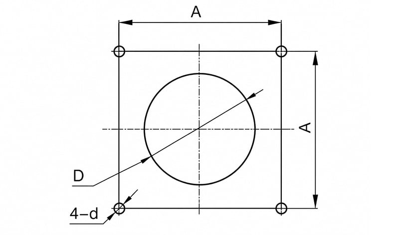
| Switch Model | A | B | d |
| HH15(QSA)-125 | 65±0.2 | Φ42+4-0 | Φ4.5+0.5-0 |
| HH15(QA)-125~200 | 65±0.2 | Φ42+4-0 | Φ4.5+0.5-0 |
| HH15(QP)-250 | 65±0.2 | Φ42+4-0 | Φ4.5+0.5-0 |
| HH15(QSA)-160~1250 | 88±0.2 | Φ63+4-0 | Φ5.5+0.5-0 |
| HH15(QA)-400~1600 | 88±0.2 | Φ63+4-0 | Φ5.5+0.5-0 |
| HH15(QP)-400~2500 | 88±0.2 | Φ63+4-0 | Φ5.5+0.5-0 |
Ordering Instructions
When placing an order, the customer must specify the switch type characteristics, voltage rating, current rating, number of poles, operating method, quantity, etc. For special orders, please consult our company’s technical department.
Example:
HH15(QSA)-125/3 400 V, fuse current 100 A, 10 units
HH15(QA)-200/3 380 V, 10 units
HH15(QP)-2000/32 380 V, 10 units
Reviews
There are no reviews yet.