


A 25 amp breaker can be a valid modular protection choice, but the rating is only defensible after the load, conductor, voltage, poles, trip curve, fault level and installation conditions have been checked. “25 A” alone is not a complete panel specification.
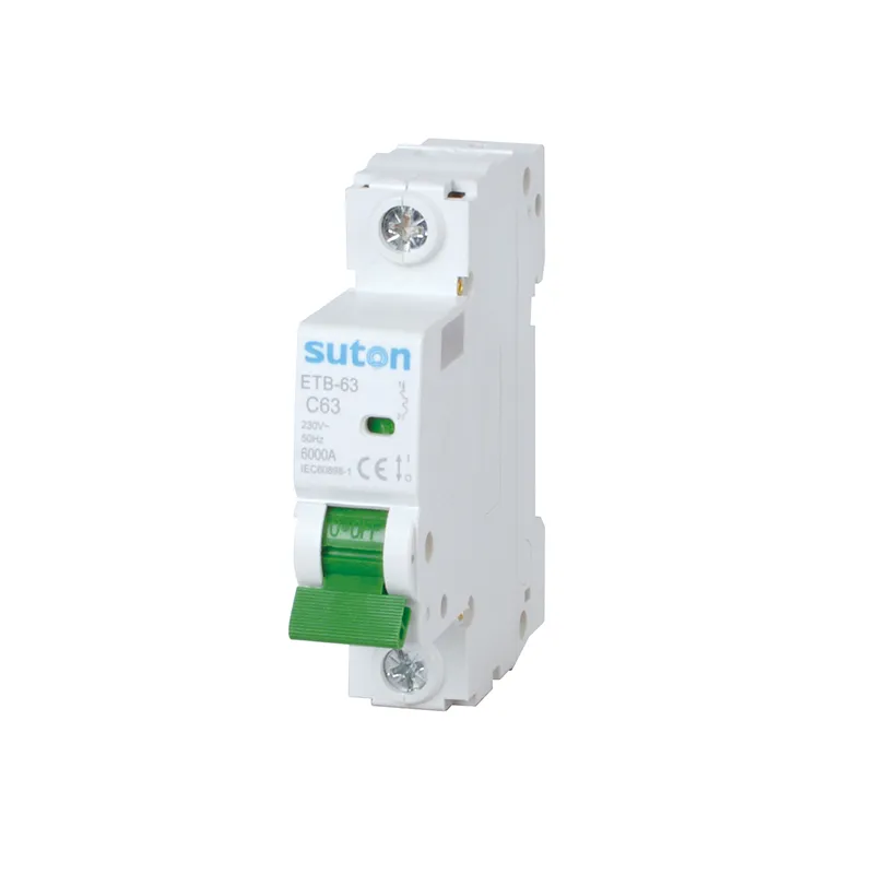
For panel builders, the safest starting point is the circuit design record—not a catalogue filter. Use the modular DIN-rail products page to evaluate families only after the protected circuit has been defined.
Where a 25 A breaker fits
The search for a 25 A breaker often begins with an appliance rating, a conductor question or a desire to stop repeated trips. Those starting points do not prove that 25 A is correct.
A legitimate selection connects three layers:
- the circuit calculation and conductor limit;
- the protective behavior required during overload, inrush and short circuit;
- the exact device ratings, poles and installation conditions.
If any layer is missing, the panel schedule should show the item as unresolved rather than silently rounding it to 20 A, 25 A or 32 A.
Verify each field separately
| Field | Project evidence required | Procurement consequence |
|---|---|---|
| Design current | calculated operating current and duty | confirms whether 25 A is above normal demand without hiding overload |
| Conductor | material, cross-section, insulation and installation method | determines the protection ceiling under applicable rules |
| Voltage and frequency | actual circuit values | must be within the device’s published rating |
| Poles | conductors to be switched/protected together | defines 1P, 2P, 3P or 4P configuration |
| Trip curve | inrush and fault-clearing requirements | separates normal starting current from an abnormal condition |
| Breaking capacity | prospective short-circuit current | must meet the calculated duty at the installation point |
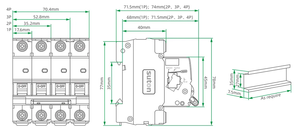
| Panel interface | mounting, terminals, busbar and accessory arrangement | prevents a correct ampere rating from becoming an incompatible build |
| Environment | ambient, altitude and adjacent-device density | may require correction or derating |
Do not turn a 25 A query into a universal wire table
Search results frequently pair 25 A with a fixed conductor size. That can be useful only inside the stated code, conductor material, temperature, installation and distance assumptions. SUTON serves multiple markets, so a global specification must keep those conditions visible.
Record the project conductor calculation and applicable rules in the design file. The breaker article should not replace them.
Compare adjacent ratings by protection outcome
The live 20 amp breaker guide and 30 amp breaker guide cover adjacent search intents. They are not a menu for automatic upsizing.
Choose 20 A, 25 A or another published rating by testing each option against the protected conductor, expected load profile, trip behavior and coordination plan. If 25 A falls between a calculated requirement and an available project-approved device, resolve the engineering basis rather than selecting the numerically closest handle marking.
Create an RFQ that can be checked
Provide these fields together:
- load type, design current and duty;
- conductor data and installation condition;
- voltage, frequency and poles;
- curve or trip requirement;
- prospective fault current and required breaking capacity;
- enclosure ambient, altitude and grouping;
- upstream/downstream coordination requirement;
- mounting, terminal and accessory needs;
- applicable standard and required evidence;
- quantity and exact series/configuration requested.
Verified SUTON 25 A modular options
The public ETB-63 Series High Breaking MCB page lists 25 A, 1P–4P configurations, B/C/D characteristics and 6 kA Icn. The public DZ47 Series Miniature Circuit Breaker page also lists 25 A among its C/D options and publishes 1P–4P configurations.
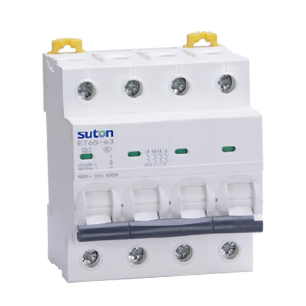
Use these pages as verified starting points. Confirm the exact voltage, pole, curve, breaking-capacity, terminal and accessory combination before releasing a BOM. A published 25 A option does not establish fit for every circuit or panel.