


A 10 amp breaker is appropriate only when the protected conductor, calculated load, voltage, pole arrangement, trip response and fault duty all support that rating. The number on the handle is one selection field—not a complete design decision.
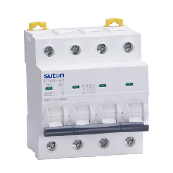
For panel builders and electrical contractors, the practical task is to document why 10 A was selected and which device configuration satisfies the circuit. Start from the modular DIN-rail product family only after the circuit inputs are known.
What a 10 A rating does—and does not—tell you
The 10 A marking identifies the breaker’s rated current under its specified conditions. It does not, by itself, establish the allowable conductor size, the load’s starting behavior, the number of protected poles or the short-circuit rating required at the installation point.
That distinction matters when a load draws less than 10 A during normal operation but has a starting or inrush current. A different trip curve may be required, yet changing the curve must not become a substitute for checking conductor protection and fault-clearing requirements.
The same caution applies to a breaker that trips repeatedly. Moving from 10 A to the next rating is not a troubleshooting shortcut. First determine whether the trip is caused by sustained overload, inrush, a fault, high ambient temperature, dense panel installation or an incorrect device characteristic.
Build the selection from independent inputs
| Selection field | What to verify | Why it changes the decision |
|---|---|---|
| Load current and duty | normal current, continuous operation, starting or inrush behavior | separates genuine overload from expected transient current |
| Protected conductor | material, cross-section, insulation, grouping and installation method | the breaker must protect the conductor under project rules |
| System voltage | rated AC/DC voltage and frequency | the device rating must cover the actual circuit |
| Poles | conductors that must be switched or protected together | a single-pole choice cannot be inferred from amperes |
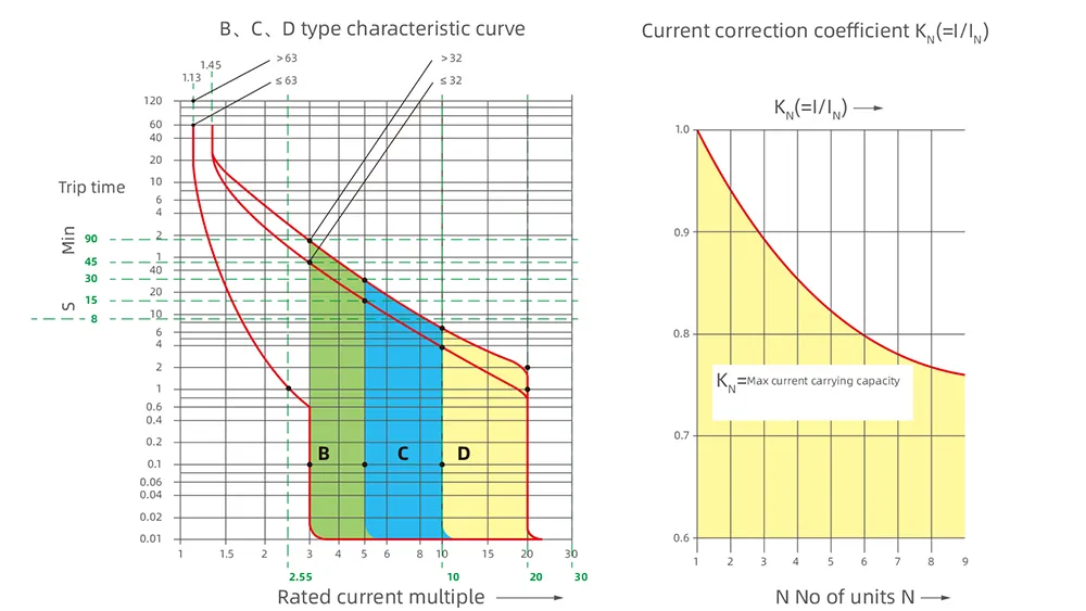
| Trip curve | load inrush and required disconnection behavior | affects instantaneous operation and nuisance-trip risk |
| Breaking capacity | prospective short-circuit current at the installation point | the device must safely interrupt the calculated fault level |
| Environment | enclosure temperature, altitude and side-by-side installation | published performance may require correction or derating |
| Coordination | upstream/downstream protective devices | affects selectivity and the extent of an outage |
This is why a global article should not give a universal wire-size answer for every 10 A circuit. Conductor rules depend on jurisdiction and installation conditions; the project calculation remains the controlling record.
When 10 A and 16 A are not interchangeable
A designer may see both ratings in the same product family and assume that 16 A provides extra margin. That reasoning is incomplete. A higher rating can reduce nuisance trips, but it can also weaken conductor protection if the circuit was designed around a lower allowable current.
Use the 15 amp breaker guide and 20 amp breaker guide to understand adjacent-rating questions, but do not select by numerical proximity. Recalculate the circuit when the rating changes.
Prepare a usable panel or RFQ handoff
Before an order or panel BOM is released, record:
- circuit designation and load type;
- calculated design current and operating duty;
- conductor material, cross-section and installation condition;
- system voltage, frequency and required poles;
- required trip curve or trip-unit behavior;
- prospective short-circuit current and required breaking capacity;
- ambient, altitude and grouping conditions;
- upstream and downstream coordination requirements;
- required auxiliary, alarm or shunt-trip accessories;
- applicable project standard and approval evidence.
The checklist prevents “10 A” from becoming an incomplete purchase description.
SUTON 10 A MCB paths to evaluate
SUTON’s public DZ47 Series Miniature Circuit Breaker page lists 10 A among its rated-current options, with 1P–4P configurations and C/D characteristics; the exact ordered combination still needs confirmation. The ETB-63 high-breaking MCB page also lists 10 A, 1P–4P, B/C/D characteristics and a published 6 kA Icn value.
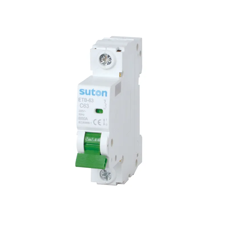
These are relevant evaluation paths, not automatic substitutions. Match the chosen series to the project’s voltage, poles, curve, fault calculation, environment and accessory needs before issuing the BOM or RFQ.