


Fifty amperes is where final circuits become small feeders — the frame decision, fault duty, and coordination evidence now matter as much as the rating.
At 50 A the circuit usually feeds an EV charging point, a workshop or kitchen sub-board, a large cooking appliance, or a small feeder to a remote enclosure. These circuits behave like infrastructure — they carry sustained current for long periods and their failure takes out a working area, not a single socket.
Important: This guide structures 50 A sub-feed selection for LV panels in line with overcurrent protection scope in IEC 60898-1 and molded-case product scope in IEC 60947-2. It cannot approve a frame, breaking capacity, or coordination result where fault-study data, load basis, or charger-manual requirements are missing — hold those inputs for engineering review before procurement.
Part 1. Turn a 50 amp sub-feed request into panel inputs
Sub-feed positions need feeder discipline even when the paperwork calls them final circuits. Plan them with duty description, load basis, and fault-study references before comparing catalogues.
| Selection factor | Why it matters for the panel | Send with quote |
|---|---|---|
| Duty description and load basis | grounds the rating and margin | yes |
| Conductor calculation reference | proves the pairing is protected | yes |
| Frame decision with fault study | fixes modular vs molded case | yes |
| Curve or settings requirement | fixes trip behavior | yes |
| Poles and neutral treatment | fixes arrangement | yes |
| Coordination expectations | demands selectivity evidence | yes |
| Residual requirements with manual references | fixes protection plan | when applicable |
| Mounting, standards, quantity | fixes assembly scope | yes |
Send the feeder story, not a bare number. Procurement teams that quote from the amp label alone often miss frame duty, coordination, or residual-integration requirements that surface at commissioning.
Part 2. Decide modular MCB or molded case at this rating
Mid ratings sit in both catalogues, and the frame decision is real.
| Decision driver | Points to modular MCB | Points to molded case |
|---|---|---|
| Breaking capacity vs fault study | modest fault levels | higher fault levels |
| Settings needed | fixed characteristics acceptable | adjustable settings wanted |
| Mounting context | DIN rail among modular devices | feeder section or separate frame |
| Downstream role | protecting one circuit | feeding a sub-board with growth |
| Accessories and signaling | basic auxiliaries | richer accessory ecosystem |
The general frame ladder is covered in the circuit breaker types guide, and molded-case specifics in the MCCB breaker guide. The schedule should record which frame was chosen and why.
Part 3. Coordinate the conductor calculation with the breaker
Conductor sizing at 50 A is a project calculation under the applicable installation rules — method, ambient, grouping, cable construction, and run length decide it, and this guide quotes no gauge table as a universal rule. Sub-feed runs are often long, so voltage drop and fault-loop performance deserve the same attention as thermal capacity.
Sustained-duty loads add a margin question. Where a feed will run near its rating for hours — charging is the obvious case — the design authority should document the loading assumption and any continuous-duty margin, so the breaker, conductor, and terminals are all selected on the same basis.
Part 4. Fix breaking capacity and selectivity evidence
Breaking capacity comes from the fault study at the installation point, not from a habit value. Feeder positions close to the supply see higher prospective currents; the delivered device marking must meet the calculated duty, and the fault-study extract belongs in the panel dossier.
Coordination now runs both directions: upstream selectivity so a sub-board fault does not black out the main board, downstream so the sub-board’s own devices trip first. Manufacturer selectivity data per pairing is the evidence; the general framework sits in the circuit breaker guide.
Part 5. Plan EV charging and sustained-duty feeds
Treat a charging feed as a small project. The charger manual is a design document: it states the required supply, any integrated residual detection, and the connection conditions — and those statements change what the panel side must provide. Where load management shares capacity among several chargers, the feed rating follows the managed limit, documented explicitly.
Residual protection deserves particular care, because charger-integrated detection and panel-side devices must be planned together rather than doubled or omitted. Record the manual references in the schedule row; the classification workflow for converter-fed circuits is the Type B screening register described in our residual-protection articles.
Part 6. Route a documented 50 A breaker inquiry
Send with the inquiry:
- duty description, load basis, and approved single-line diagram
- conductor calculation reference and installation method summary
- frame decision with fault-study extract
- required curve or settings, poles, and coordination expectations
- residual requirements with charger or equipment manual references, if applicable
- mounting interface, applicable standards, and quantity
Require suppliers to declare the exact offered marking, frame, settings range, breaking capacity, and installation instructions against the feeder schedule. Hold the engineering decision when fault data or coordination evidence is incomplete.
Fit Boundary: this guide structures 50 A sub-feed selection inputs. It does not perform fault studies or conductor calculations, does not interpret charger manuals remotely, and cannot decide the frame where fault data is missing. Close those inputs with the design authority before pricing.
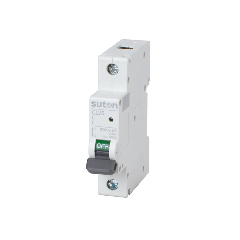
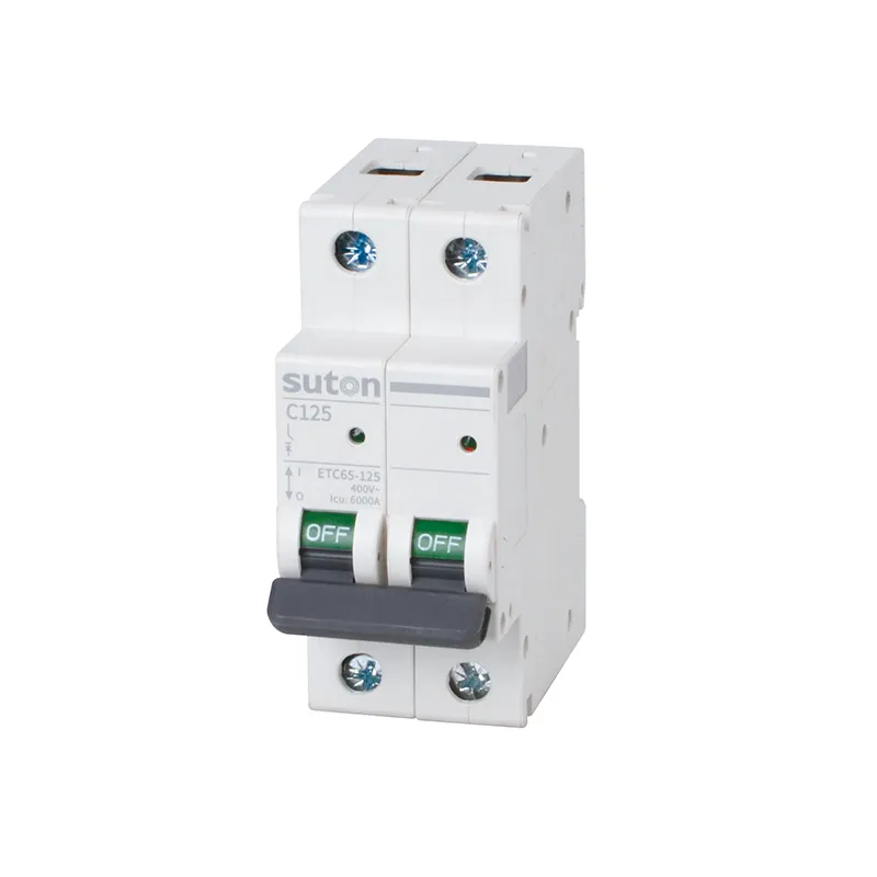
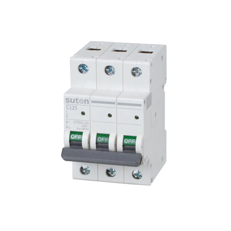
For a product recommendation starting point, review SUTON’s ETC65-125 series route at the modular end and the ETM1 series molded case circuit breaker route where the frame decision lands on molded case. Ratings, curves, settings, and certifications are model-specific — confirm datasheets against the fault study, then send the feeder schedule through Contact SUTON for a documented review.
Sub-feed records that pay for themselves
Give every 50 A position a one-page feed file: duty description, load basis, conductor reference, frame decision, fault-study extract, coordination evidence, and — for charging — the manual references. The file costs an hour at design time.
It pays out at every later event. A tripped feed gets diagnosed against documented assumptions; a capacity question gets answered from the margin decision; an added charger gets evaluated against the managed limit instead of an anecdote.
Volume programs — fleet depots, apartment charging retrofits — should standardize the feed file as a template. Identical documentation across dozens of positions turns commissioning and audits into repetition, which is exactly what volume programs need.
FAQ
What is a 50 amp breaker used for?
Sub-feed duties: EV charging points, workshop or kitchen sub-boards, large appliances, and small feeders to remote enclosures.
What wire size does a 50 amp breaker need?
That is a project calculation under the applicable installation rules; method, ambient, grouping, cable type, and run length decide it, with voltage drop checked on long runs.
Should a 50 amp breaker be modular or molded case?
Follow the fault study, settings needs, and mounting context: modest duties suit modular devices, while higher fault levels or adjustable settings point to molded case.
What breaking capacity does a 50 amp breaker need?
At least the prospective fault current calculated at the installation point; the delivered marking must meet the study, not a habit value.
How is a 50 amp EV charging feed protected?
Per the charger manual and the design: rating against the managed load, residual protection planned with any charger-integrated detection, and documentation in the schedule.
What data belongs in a 50 amp breaker RFQ?
Provide the duty description, load basis, conductor reference, frame decision with fault data, curve or settings, poles, coordination expectations, residual requirements, mounting, standards, and quantity.