Earthing switch mechanical interlocks restrict incompatible switching states, such as connecting a circuit to its supply while the associated earthing path is engaged. Their value depends on the exact mechanism, the circuit boundary and the approved operating sequence. An interlock is not proof that conductors are dead, and a live indication lamp is not a substitute for the required voltage verification. For a low-voltage panel, specify the interlock as a set of observable, testable functions before selecting the switch. This guide focuses on procurement and acceptance of an isolator with an integrated earthing function, rather than providing a switching procedure.
Identify the circuit that the earthing function actually serves
Start with a single-line diagram showing the supply, outgoing circuit, alternate sources, neutral arrangement and the location of the proposed earthing connection. Mark which conductor sections the mechanism can connect to earth. A switch mounted near a feeder does not automatically earth the whole feeder, the busbar or an adjacent compartment. A drawing that only says “earthing provided” leaves an important engineering question unanswered.
Separate the equipment being maintained from the equipment that must remain energized. Consider incoming terminals, auxiliary supplies, generators, photovoltaic sources and stored energy in connected equipment. The drawing should identify the relevant isolation points and the area to which access may eventually be permitted. The responsible engineer must decide whether an integrated earthing function suits that boundary and what additional controls are needed. Do not infer a system grounding design from a product photograph.
Distinguish an interlock from an indication
A mechanical interlock physically restricts a defined movement or condition. An auxiliary contact reports a state to another circuit. A live indication function provides information about voltage according to its design and connection. These features can work together, but they do different jobs. A remote display showing “earthed” cannot establish that every conductor is safely isolated, and an indicator failure must not silently become permission to operate.
For each required feature, record the input condition, the prohibited operation and the observable result. For example, the specification may require a defined relationship between the service position and the earthing position. The supplier should explain how that relationship is implemented in the exact offered model. Avoid phrases such as “complete safety interlocking” without a function description. They are difficult to test and can hide differences between a standard mechanism and an optional accessory.
Read the actual HS11FD product evidence carefully
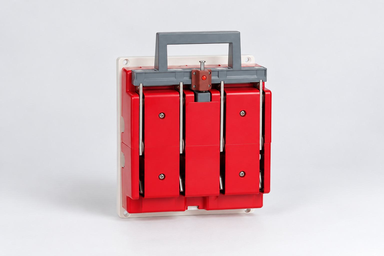
O SUTON HS11FD isolator with earthing function is described as a development of a knife-type changeover design. Its published features include a mechanical interlocking mechanism, opening and closing signal outputs, an earthing function and live indication. The product description identifies energized and earthing states. These statements establish a relevant product family for an inquiry; they do not establish a complete site operating sequence.
The same product page asks the buyer to specify whether the neutral pole is on the left or right, because the live indication circuit has phase-sequence requirements for its power take-off. This is a practical reason to freeze the wiring arrangement before ordering. A neutral position that is treated as a minor mechanical detail can affect the intended connection scheme. Request the exact terminal diagram, model designation, signal contact diagram and installation instructions for the selected version.
The published table includes current-dependent short-time withstand figures. Retain the complete table and its applicable time basis rather than copying an isolated number into the panel schedule. This article deliberately does not use that table to approve a prospective fault current. That requires the exact rating conditions, upstream protection and assembly assessment for the offered equipment.
Build a function-based acceptance schedule
| Rever item | Evidence requested | Pergunta de aceitação |
|---|---|---|
| Work boundary | Single-line and source map | Which conductors can the earthing function affect? |
| Interlock | Exact mechanism description | Which incompatible state is physically restricted? |
| Indicação | Voltage and state indication diagrams | What does each signal establish and not establish? |
| Neutro | Approved terminal diagram | Is the left/right neutral arrangement correct? |
| Access | Outline and operating envelope | Can the complete mechanism be inspected? |
| Records | Approved test method and revision | Do delivered functions match the documents? |
Use this schedule to structure the supplier response and commissioning record. It is a qualitative review tool, not a test instruction. Each accepted row should point to a drawing, manual section or approved test record. If the supplier cannot identify which model or accessory provides a function, keep that row open. Do not accept a demonstration on a visually similar product as evidence for the delivered assembly.
O Guia geral de interruptores e desconectadores explains how the isolation boundary fits the panel layout. The present article adds the earthing-state and interlock questions. Keep those scopes separate in the documentation so that a general isolation checklist does not replace the specific interlock review.
Review all paths that can defeat the intended boundary
An interlock acts within a mechanism or control arrangement. It cannot prevent every external wiring error. A backfeed from another source, an incorrect neutral connection or a misplaced auxiliary supply can leave a conductor energized even when the switch has reached its intended position. The design review must therefore reconcile the mechanical state with the electrical diagram and the sources connected to the work boundary.
Examine normal supply, alternate supply, maintenance, generator and any temporary test modes included in the project. Record whether a temporary lead or test supply changes the conditions assumed by the indication circuit. Mark the approved connection points and identify any state that the design does not permit. This is particularly important when a replacement switch uses a different terminal arrangement from the original.
O Orientação da HSE sobre trabalho próximo à eletricidade explains that suitable isolation, securing against reconnection and reliable verification all matter. Its general principles support the work-control discussion; the site procedure and applicable local rules remain decisive. Do not translate a generic safety publication into a product-specific sequence that has not been approved.
Plan the indication and signal interface
Prepare a signal list for the panel builder and controls team. Identify which physical state each auxiliary output represents, how the contact behaves when the switch moves between defined states, and what the monitoring system should display if its control supply fails. Specify the contact configuration and electrical duty from the actual accessory documentation. A contact suitable for a low-energy input is not automatically suitable for a different control load.
The acceptance team should compare local indications with the relevant remote status under the approved test method. Record intentional differences, such as a local mechanical state being available when an unpowered display is blank. The useful outcome is an understandable indication system, not simply a collection of green lamps. Any state that operators cannot interpret confidently should be resolved before handover.
Keep mechanism access and maintenance realistic
Allow space for the complete movement, handle access, barriers, mounting hardware and the required maintenance approach. An interlock can be correctly designed yet impossible to inspect after adjacent equipment is installed. Request the actual outline drawing and show the operating envelope on the panel layout. Check that doors, wiring ducts and cable bends do not obstruct the mechanism.
Do not modify a stop, lock or linkage to resolve a layout conflict. Unexpected resistance, an ambiguous state or disagreement between indication and mechanism requires investigation by authorized personnel using the exact documentation. The door-coupled handle interlock guide covers a related enclosure interface; it does not establish compatibility with an integrated earthing mechanism. Different interlocks can control different hazards within the same assembly.
Require a controlled commissioning record
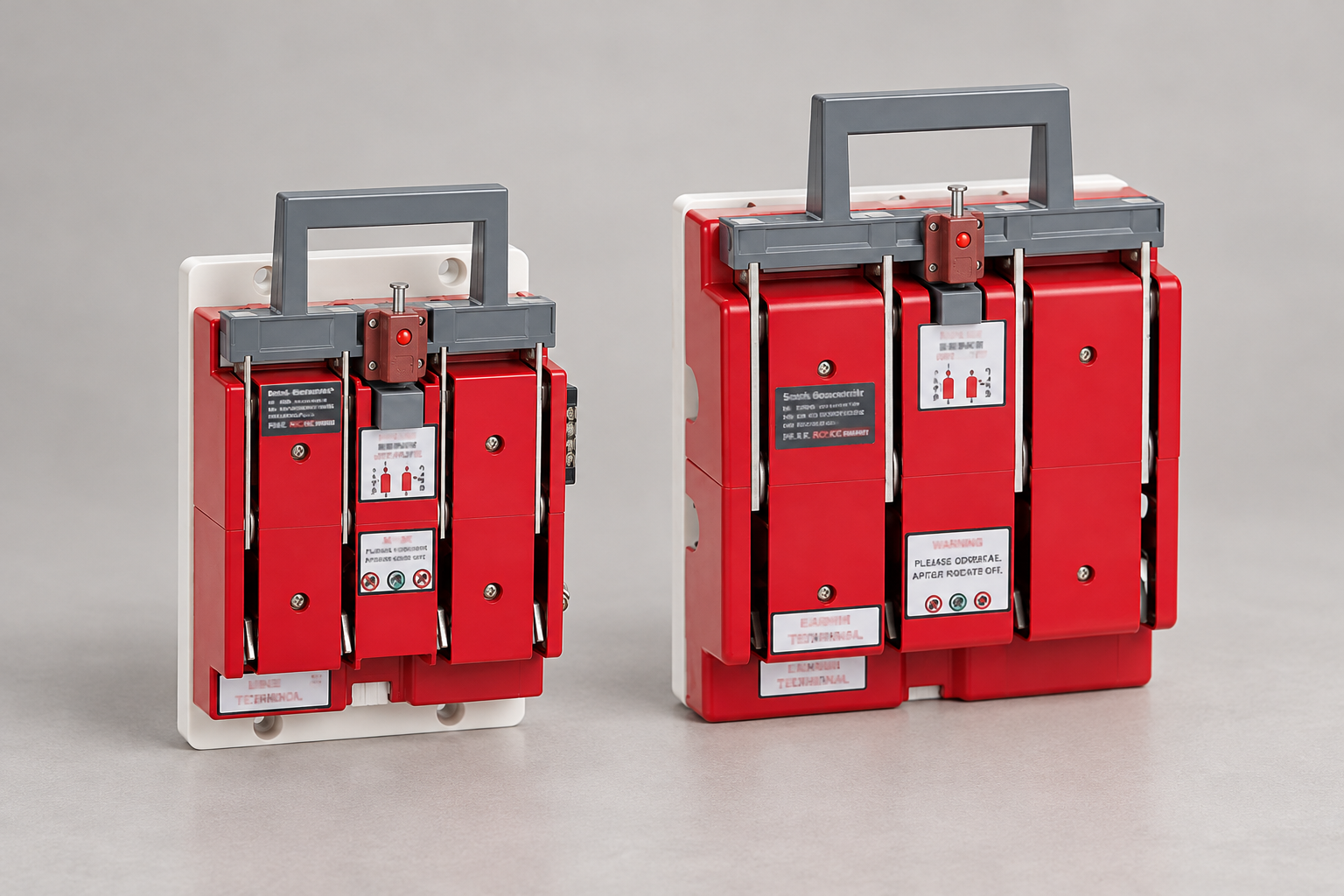
Before energization, the approved acceptance plan should identify device identity, drawing revision, permitted functions, expected signals and the responsible person. Describe tests by their intended result and refer to the approved manufacturer or project method for execution. This article does not prescribe live manipulation, test voltages or a universal handle sequence.
Retain discrepancies and their resolution. If a contact behaves differently from the drawing, resolve whether the drawing, wiring, accessory or assumption is wrong. Do not simply invert a display label until it looks plausible. The record should show the delivered condition and the condition finally accepted. Link it to the broader circuit-breaker commissioning record where the panel contains protective devices, while preserving the isolator's separate acceptance scope.
Prepare an inquiry that permits a meaningful answer
Send SUTON the single-line diagram, exact work boundary, supply and pole arrangement, requested current and voltage, neutral position, mounting method, indication requirements, control interface and required documents. Identify the requested earthing and interlock functions individually. Ask which features are standard, which are optional and which require a different product.
Include the environment and maintenance access conditions. The published HS11FD service conditions are bounded; they should not be treated as approval for unusual altitude, condensation, vibration or corrosive exposure. Where a condition falls outside the listed range, obtain a written response for that application. A quotation becomes useful when it answers the controlled requirement rather than repeating a family description.
For the safety-management context, HSE's guidance on working on electrical equipment emphasizes planning and secure control of energy sources. It supports keeping the procedure and the equipment evidence together. Neither that guidance nor this article replaces the competent person's responsibility for the installed system.
Perguntas frequentes
Does an earthing interlock prove that the circuit is dead?
No. It restricts specified incompatible states. Isolation from every relevant source, reliable voltage verification and the approved work procedure still need separate evidence.
Is a live indication lamp the same as an approved voltage test?
No. Its function and limitations depend on the product and its connections. Use the verification method required by the approved procedure rather than treating a lamp as universal proof.
What should an HS11FD inquiry identify first?
Identify the circuit boundary, supply and pole arrangement, neutral position, required earthing and interlock functions, signal interface and exact documents needed for engineering acceptance.
Vídeo educativo
SELECT Safe Isolation Animation 2024 by SELECT. SELECT is the Scottish electrical trade association. This neutral training animation supports the safe-isolation discussion; it does not establish a SUTON-specific operating sequence or replace the approved site procedure.