SPD coordination means selecting and connecting surge protective devices so that their declared duties work together across the installation. Type 1, Type 2 and Type 3 devices are not three interchangeable levels of the same product, and adding more devices does not automatically produce a coordinated system. Start with the lightning and surge assessment, identify the protected equipment and all relevant incoming services, then obtain manufacturer-supported combinations and connection conditions. This guide explains how panel buyers document a staged protection strategy without treating a simple cascade diagram or matching brand name as proof of compatibility.
Give each stage a defined job
A Type 1 SPD is associated with lightning-current duty where that duty is required by the installation assessment. A Type 2 device addresses its declared surge protection role at appropriate distribution locations. A Type 3 device provides supplementary equipment-level protection under its stated conditions. Combined products can perform more than one declared role, but the claims must apply to the exact model.
The important procurement question is why a particular stage is needed at a particular location. A service entrance, a sub-distribution board and sensitive equipment may face different duties and connection conditions. Do not select every location by copying the largest printed kA rating from the main-board device.
O IET's explanation of SPDs describes these distinct roles and the need to coordinate multiple devices. Its discussion uses a UK installation framework. For other projects, confirm the adopted rules, terminology and exact product instructions rather than assuming every classification system is identical.
Map the installation before comparing products
Create a single-line diagram showing the supply entry, main board, sub-boards, relevant outgoing circuits and the equipment being protected. Add cable routes that leave or enter the building and the location of any external lightning-protection system. Note the supply and earthing arrangement at each intended SPD location.
Power wiring is only one route by which a transient can affect equipment. Signal, communications and other conductive services may also need assessment. A machine connected to protected power and an unreviewed external data cable can remain exposed through the second path. Coordinate the relevant interfaces rather than assuming a power-board SPD solves every entry route.
Identify any built-in protection in equipment and request its documentation. The phrase surge protected does not establish its classification, test duty, replacement requirements or compatibility with upstream devices. Treat undocumented built-in protection as an unanswered input, not a guaranteed stage.
Understand what coordination evidence must show
Coordination concerns how devices respond together, including their energy duty, voltage protection and installation conditions. A lower downstream Up value alone does not prove that the downstream device will remain within its permitted duty when an upstream device operates.
Request a manufacturer coordination table, tested combination or other appropriate engineering evidence naming the exact devices. Check the applicable supply arrangement, surge class, connection conditions and any required separation or decoupling measures. A catalog illustration showing three device symbols is a concept drawing, not necessarily a tested combination.
Do not assume that devices from the same brand are automatically coordinated. Product families may have different technologies and intended uses. Conversely, devices from different manufacturers need a supported suitability assessment; a shared nominal voltage is not enough. Keep the evidence attached to the approved bill of materials.
Use a stage-by-stage review table
| Stage or interface | Defined role | Prova necessária |
|---|---|---|
| Type 1 where required | Declared lightning-current duty at the assessed location | Exact model classification and installation conditions |
| Type 2 | Declared surge-limiting duty at the relevant distribution point | Supported combination with adjacent stages |
| Type 3 | Supplementary protection close to equipment | Upstream compatibility and local connection conditions |
| Combined device | More than one documented duty in one assembly | Claims for exact base and cartridge configuration |
| Signal and other services | Address other relevant transient entry paths | Interface-specific protection and bonding assessment |
| Every stage | Safe branch protection and maintainability | Fault-duty conditions, monitoring and replacement codes |
The table organizes the assessment without prescribing a universal arrangement. A building may require combined devices, additional stages or different treatment for separate services. The final design should state the intended protective function at each location and the evidence supporting the combination.
Compare protection paths as well as classifications. A device suitable for one earthing arrangement cannot be assumed compatible with another stage merely because both are called Type 2. The SPD earthing-system guide explains that earlier system review.
Separate waveform ratings from location labels
In, Imax and Iimp describe declared surge-current characteristics under specific tests. A number associated with one waveform or duty is not a direct substitute for another. Confirm the classification and conditions before comparing two candidates.
The rated continuous voltage must match the actual protective paths and supply conditions. The voltage protection level must be suitable for the protected equipment within the installed design. These checks remain necessary even when the upstream and downstream combination appears in a coordination table.
Read SPD Uc, Up, In and Imax ratings for the distinction between these symbols. Then evaluate the exact models as an assembly. Avoid a purchasing spreadsheet that ranks products by a single kA column while omitting their voltage, topology and coordination conditions.
Review the spacing and connection requirements
Some combinations depend on defined cable conditions or additional measures. Do not use a universal distance rule as proof that any two devices will coordinate. The required arrangement must come from the applicable evidence and installation instructions.
Keep separation between stages distinct from the connecting lead length at each stage. A long cable between boards does not excuse unnecessarily long leads at the SPD. Likewise, short local leads do not demonstrate that an arbitrary downstream device is compatible with the upstream stage.
The article on Comprimento da linha de comando do SPD explains the local connection review. For coordination, record both the inter-stage conditions and the actual connection route at every board. This prevents a concept drawing from concealing a physically unsuitable panel layout.
Check backup protection independently at every stage
Each SPD must meet its declared short-circuit and external protective-device requirements at its own installation point. The available fault current may differ between a main board and a remote sub-board. Copying one branch protection schedule to every location can miss those differences.
A dedicated branch protective device can affect both continuity and monitoring. If it disconnects the SPD while leaving the equipment energized, maintenance staff need to know that surge protection is unavailable. If shared upstream protection operates, a larger part of the installation may lose supply. Record the intended failure consequence.
O backup fuse and breaker sizing guide gives a structured review method. A coordination table for surge stages does not automatically approve every external fuse, breaker or conductor used in the branch.
Combined devices still need an installation review
A Type 1+2 device can simplify part of a design when its combined duties and installation conditions match the project. That does not remove the need to consider sensitive downstream equipment, other services or the distance and arrangement between the device and the protected load.
Check that the combined classification belongs to the exact offered assembly. A family brochure may discuss several variants with different test claims. Verify base and cartridge codes, voltage, protection paths and the relevant performance evidence together.
Where a combined device replaces two separate stages, document what changed in the protection strategy and why the new arrangement is supported. Do not remove a downstream stage simply because the upstream quotation contains a plus sign in the classification.
Apply the method to a small industrial facility
Consider a facility with a main switchboard, a workshop sub-board and a control cabinet connected to an outdoor sensor network. Begin by identifying the surge and lightning exposure, the earthing arrangement and the equipment withstand requirements. Decide which entry points and locations need protection before selecting products.
Next, obtain a supported main-board and sub-board combination. Review the local connections and any stage-separation conditions. Assess supplementary protection at the control equipment and the external signal route. Confirm that built-in equipment protection, if credited, is documented for the intended role.
Finally, record the backup protection and monitoring for every stage. This example intentionally does not assign numeric ratings without site evidence. Its purpose is to show how a coordinated system is assembled from documented functions, not from a shopping list of three different product types.
Control substitutions and future changes
Coordination can be lost when a maintenance replacement has the same physical dimensions but different electrical characteristics. Record the approved base and cartridge codes for every location. Specify whether alternative models require a new suitability review.
Changes to supply voltage, source configuration, cable routes, protected equipment or lightning protection can also affect the design. The original coordination evidence should be reviewed when those inputs change. Keep revision history so the site can identify which arrangement was approved and when.
At delivery, verify the actual markings against the schedule and retain the instructions. At handover, document indicators, remote contacts and the response to a failed or disconnected stage. A healthy signal should describe the condition actually monitored, not imply that every protective path and service has been independently tested.
Install and inspect using the approved procedures
Installation and electrical testing require competent personnel and an appropriate safe system of work. HSE guidance explains the need to identify hazards and control the relevant energy sources. It does not replace the exact product instructions or provide a generic method for testing an SPD in a live panel.
Follow the manufacturer's requirements for inspection, replacement and the treatment of SPDs during electrical tests. Do not infer full protection performance from a status window alone. Its meaning depends on the particular device and monitoring arrangement.
Maintenance records should identify which stage was inspected or replaced and why. When a branch protective device operates, investigate the condition using the approved procedure. Replacing a cartridge without checking the rest of the affected arrangement can leave the original issue unresolved.
Request a documented SUTON protection package
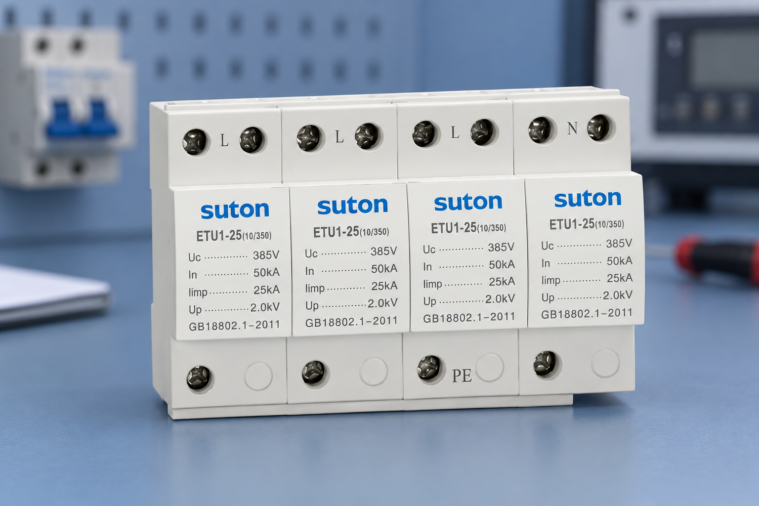
Utilize SUTON ETU1 surge protective device family as the starting point for a specific inquiry. Supply the single-line diagram, earthing arrangement, required stage duties, voltages, fault-current information, cable conditions and equipment requirements. Ask for exact proposed models and coordination evidence rather than a generic family recommendation.
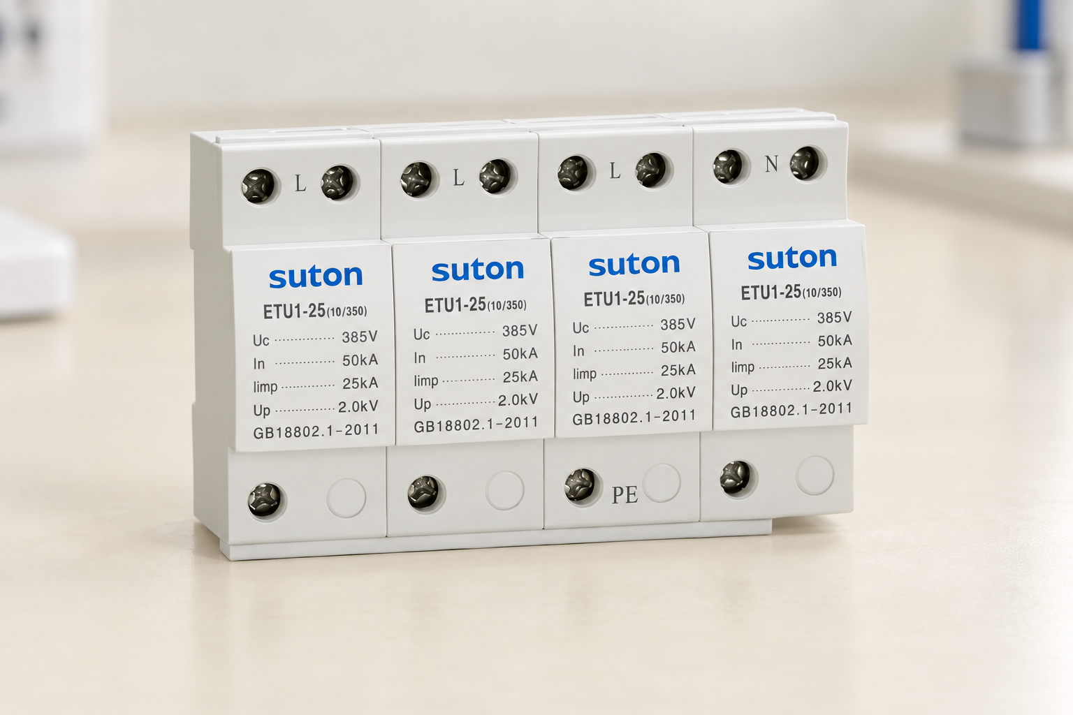
The photographed ETU1 exterior in this article does not establish every Type 1, Type 2 or Type 3 variant. The broader Guia de seleção de SPD do tipo 2 supports the product review, but the final package must resolve the complete installation. Keep any unsupported stage or combination marked as unresolved until appropriate evidence is available.
Perguntas frequentes
Does installing all three SPD types guarantee coordination?
No. The exact devices, duties, voltage ratings, protection paths and installation conditions must be compatible and supported by appropriate evidence.
Is one manufacturer's brand name enough to establish compatibility?
No. Obtain evidence for the exact models and conditions. Products sharing a brand or enclosure style may perform different functions.
Can a Type 3 device replace upstream surge protection?
No. Its supplementary role and installation conditions must be assessed within the complete protection strategy. It must not be treated as an unconditional substitute for required upstream protection.
Referências e âmbito de aplicação
Fundamentos técnicos: Explicação da proteção contra surtos do IET, Guia de proteção contra BEAMA, Orientação da HSE sobre segurança elétrica. Aplique os padrões adotados pelo projeto e as instruções de uso do produto exato. As ilustrações do produto mostram a família SUTON fotografada e não estabelecem classificações ou aprovações de instalação não listadas.
Vídeo educativo
Proteção contra surtos – Fundamentos, da IAEI – Autoridade de Execução Eletrônica, fornece informações gerais sobre proteção contra surtos. Não estabelece classificações específicas para modelos ou substitui o projeto do projeto. Sua discussão sobre um quadro de instalação deve ser verificada em relação às normas adotadas pelo projeto.