


A DC SPD for solar PV must be designed and documented for the photovoltaic DC circuit, with voltage, protection paths, fault-current capability and surge duty matched to the actual array and inverter. An AC surge protector with a similar enclosure or a large kA label is not an acceptable substitute. Begin with the array's maximum voltage under the design temperature conditions, the earthing arrangement, inverter requirements and lightning-risk assessment. This guide helps buyers prepare a verifiable specification for string and combiner-box applications while keeping an AC product-family reference separate from an approved PV DC device.
Separate the PV DC side from the inverter AC side
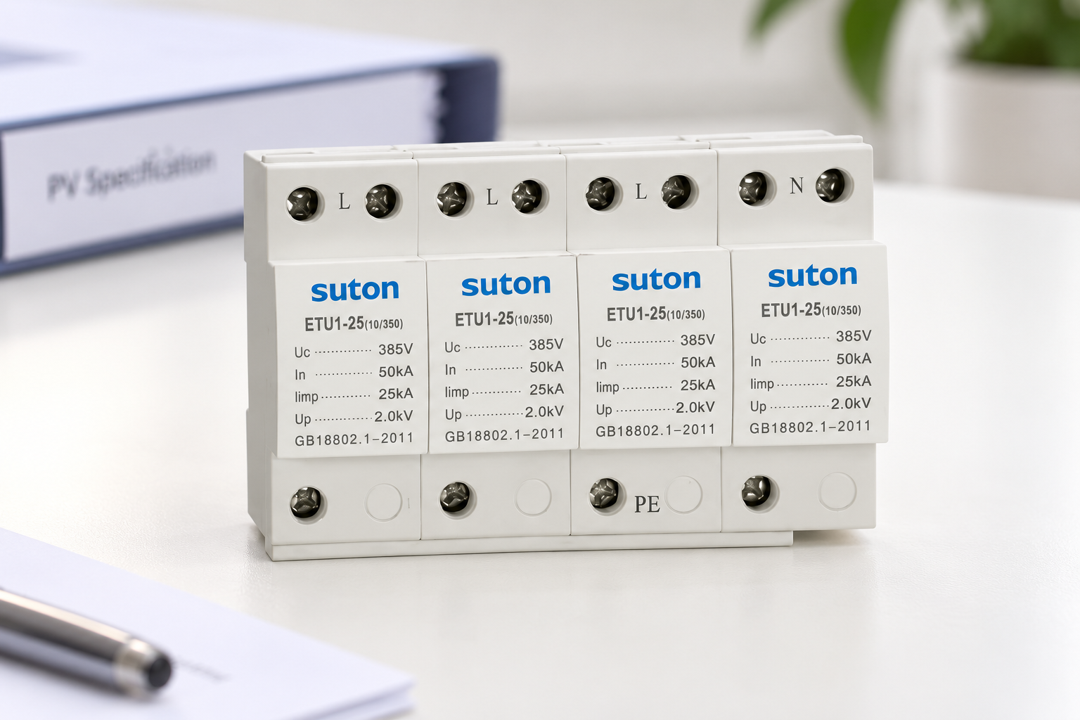
A solar installation has different electrical circuits on the array side and the grid side of the inverter. Protection selected for the AC output does not establish suitability for the DC input. The inverter is not a reason to assume that a surge protector can be moved from one side to the other.
For broader surge-device duties and panel procurement questions, see Seleção do SPD do tipo 2. That AC-oriented guide is background only and does not establish PV DC suitability.
PV circuits have source and interruption characteristics that require suitable equipment. Check that the exact SPD is declared for photovoltaic DC service. A general DC label may also be insufficient if it describes another source, such as a battery system, without covering the PV application. Similarly, a PV device's evidence must not be extended automatically to energy-storage circuits.
IEC 61643-31 addresses SPDs for the DC side of PV installations and sets out a specific scope. The official IEC publication summary is a useful starting point for identifying the appropriate evidence, but a standard number printed in a quotation is not independent proof that a particular offered model complies.
Establish the array's maximum voltage
Collect the module datasheet, the number of modules in series, the relevant temperature coefficient and the project's minimum design cell temperature assumptions. The array can have a higher open-circuit voltage in cold conditions than under the module's standard test conditions. Nominal inverter operating voltage alone is therefore not the whole selection input.
For a conceptual string calculation, multiply the module open-circuit voltage at the design condition by the number in series. If a documented linear temperature correction is used, the calculation must follow the module manufacturer's coefficient definition and units. A coefficient expressed as percent per degree must be converted appropriately; it is not the same input as volts per degree.
The approved design must account for applicable tolerances and rules. Do not apply an unexplained universal multiplier copied from a marketplace listing. Record the resulting maximum voltage, its source assumptions and the exact SPD continuous PV voltage requirement together so a reviewer can reproduce the decision.
An illustrative calculation with stated limits
Suppose a hypothetical module has a corrected open-circuit voltage of 48 V at the project's design condition, and a string contains 20 modules. The corresponding string value is 20 × 48 V = 960 V. These are illustrative inputs, not SUTON specifications or values for an actual array.
That result does not automatically select an SPD with a particular voltage marking. The designer must apply the required margins and instructions, check the inverter limit and identify the relevant protection-path ratings. The example demonstrates arithmetic only; it does not supply a complete design rule.
Retain the unrounded calculation and the approved specification. If the module type, string length or temperature assumptions change, review the SPD selection. A replacement inverter can also change the equipment-side requirements even when the modules remain the same.
Confirm the protection paths and earthing arrangement
PV arrays can use different grounding and insulation arrangements. The SPD circuit must be supported for the actual configuration and the inverter's requirements. Identify the positive, negative and protective-earth connections and obtain the internal protective circuit for the exact product.
Do not select a two-module or three-module device from pole count alone. The paths and internal elements determine its behavior. An approved drawing should show how the device connects and what conditions it is designed to withstand, including relevant abnormal states. A diagram for a different grounded or ungrounded circuit may not apply.
The AC-focused SPD earthing-system guide explains the general importance of identifying the system, but its TT and TN diagrams must not be transferred blindly to a PV DC array. Obtain PV-specific instructions instead of improvising from an AC product photo.
Build a PV-specific evidence checklist
| Specification input | Evidência necessária | Reason |
|---|---|---|
| Array maximum voltage | Module data, series count and approved temperature correction | Avoid selecting from nominal voltage alone |
| PV DC suitability | Exact photovoltaic model declaration and relevant test evidence | Exclude unsupported AC or general DC substitutions |
| Camadas de proteção | PV-specific circuit and approved grounding arrangement | Match array and inverter configuration |
| Fault capability | Source-current assessment and declared PV short-circuit conditions | Verify safe device and branch behavior |
| Surge duty | Site lightning assessment and required classification | Match the intended protection role |
| Instalação | Enclosure, routing, monitoring and replacement instructions | Maintain the documented installed arrangement |
Use the checklist to compare complete offered assemblies. If the base and replaceable modules have separate codes, request both. Ensure the evidence names the same configuration that will be delivered. Similar housings can conceal different continuous voltage ratings or circuits.
The table avoids prescribing numeric ratings without the array design. It also keeps the protection device separate from a combiner-box enclosure. A box marketed for solar use does not prove that every component inside it is suitable for the particular array.
Choose surge duty from the site assessment
The need for Type 1, Type 2 or a combined device depends on the lightning-protection arrangement, expected surge exposure and applicable installation rules. A rooftop array, long outdoor DC routes and equipment at different locations all need to be considered in the complete assessment.
Do not select solely by the largest printed discharge-current value. Confirm the relevant test classification and waveform. A value declared under one test cannot be substituted casually for another duty. The guide to SPD rating symbols gives general background, while the final PV selection must use the specific DC documentation.
For buildings with an external lightning-protection system, involve the lightning-protection designer. Whether separation is maintained and how services enter the protected zones can affect the protection strategy. A generic internet distance rule should not replace that project assessment.
Review fault-current capability and disconnection
A PV SPD must be suitable for the available source current and relevant fault conditions. Request the declared PV short-circuit capability and any external protection requirements. Where several strings connect in a combiner, the possible contribution from the array must be evaluated for the actual circuit.
An internal thermal function does not by itself establish every required short-circuit or source-isolation condition. The external protective device, if required, must be approved for the DC duty and coordinated with the SPD. An AC breaker selected by ampere marking alone is not adequate evidence.
Keep the review of string fuses, isolators and surge protection distinct. They have related but different functions. The method in SPD backup protection sizing is useful for organizing evidence, but an AC coordination table must not be used as approval for a PV DC branch.
Place protection within the complete layout
Identify the array, combiner boxes, DC cable routes and inverter input locations on the design. Then assess where SPDs are needed and how multiple devices will be coordinated. An inverter's built-in protection should be documented, including its type and limitations, rather than assumed from a marketing sentence.
Connection length, conductor routing and bonding affect the installed protection. An SPD inside a combiner box cannot compensate for every inappropriate cable route or equipment-side connection. Review the physical layout early, while there is still room to place components appropriately.
Environmental conditions also matter. The enclosure, moisture exposure, ambient temperature, mounting conditions and maintenance access must suit the location. Avoid using a rooftop enclosure's external rating as proof that each internal product meets all thermal and electrical conditions.
Keep commissioning within the approved procedure
PV conductors can remain energized by the array even after parts of the installation are disconnected. Isolation needs a procedure appropriate to the actual sources and equipment. HSE's safe-working guidance explains the importance of identifying sources and confirming isolation; it is not a PV-specific connection instruction.
Before acceptance, verify the exact SPD codes, documented voltage, terminals, monitoring functions and replacement modules against the approved schedule. Follow the manufacturer's instructions concerning electrical tests and the treatment of protective components during those tests. Do not assume that an ordinary insulation test can be applied through an installed SPD.
At handover, record the location and status indication of each stage. Maintenance staff should be able to distinguish an inverter fault, a branch protection operation and an SPD replacement requirement. An inaccessible indicator or unclear spare-part code weakens a technically suitable design.
Prepare a clear SUTON procurement request
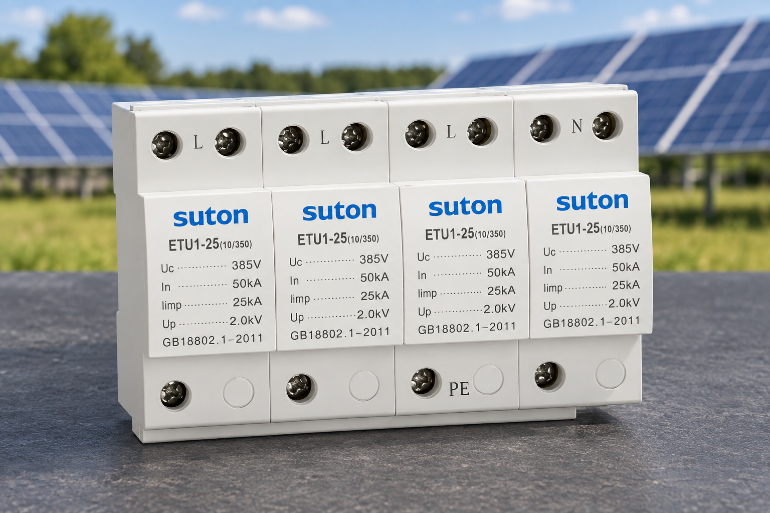
O Página da família SUTON ETU1 shows a surge-protection product reference, but the photograph used here is not evidence of PV DC suitability. It is included to show why appearance and family branding are insufficient for a DC selection. Request a separately documented PV DC option if available, and do not approve it without the relevant model evidence.
For broader solar switching requirements, the SUTON ETZM PV molded-case DC breaker is a different product category. A DC circuit breaker does not replace an SPD. Identify the required function clearly in the inquiry so these products are not confused.
Send the module and inverter data, string arrangement, corrected maximum voltage, expected source current, grounding arrangement, lightning assessment, enclosure conditions and required monitoring. Ask for the proposed SPD's exact code, PV test evidence, circuit diagram, backup protection and replacement instructions. If no suitable PV SPD documentation is supplied, the correct procurement status is unresolved.
Perguntas frequentes
Can an AC SPD be used on a solar string if its voltage marking is high enough?
No. Voltage alone does not establish PV DC suitability. The device needs documented photovoltaic DC service, compatible protection paths and the required fault and surge performance.
Does the inverter's nominal DC voltage determine the SPD rating?
No. Review maximum array voltage under the approved design conditions, the inverter requirements and the exact SPD instructions. Nominal operating voltage is only one input.
Does a DC breaker provide surge protection?
No. A DC breaker and an SPD perform different protective functions. Their specifications and coordination must be reviewed separately within the complete PV design.
Referências e âmbito de aplicação
Fundamentos técnicos: IEC photovoltaic SPD publication scope, Orientação da HSE sobre segurança elétrica, Guia de proteção contra BEAMA. Aplique os padrões adotados pelo projeto e as instruções de uso do produto exato. As ilustrações do produto mostram a família SUTON fotografada e não estabelecem classificações ou aprovações de instalação não listadas.
Vídeo educativo
Surge Protection – Fundamentals, by IAEI – The Electrical Enforcement Authority, provides general educational background on transient protection. It does not establish model-specific ratings or replace the project design. For this PV article, use it only for general surge background; PV DC selection requires the separate photovoltaic evidence discussed above.