Busbar support spacing must be selected for the actual conductor arrangement, support system and short-circuit duty. There is no universal distance that makes every low-voltage panel safe. Peak fault current drives mechanical loading, while fault duration and current also affect thermal duty. A verified assembly layout or an appropriate engineering assessment must establish the permitted span. For purchasers and panel builders, the practical task is to connect the support drawing, conductor details, fault study and verification record before approving manufacture. This guide explains those inputs and the mistakes that commonly break that connection.
Separate support span from electrical spacing
Support spacing is the distance between structural restraint points along a conductor. Phase spacing is the separation between phase conductors. Clearance and creepage describe insulation paths. These dimensions interact in a finished assembly, but they answer different questions. Moving the phases farther apart may reduce magnetic interaction while changing terminal alignment, enclosure space and insulation arrangements. Adding a support can introduce new fasteners or conductive parts near an insulation path.
Use a dimensioned drawing that identifies each type of distance explicitly. The busbar clearance and creepage guide covers the insulation questions. This article focuses on structural restraint. A support distance copied from a photograph does not establish either mechanical adequacy or electrical insulation compliance, especially when the concealed mounting arrangement is unknown.
Begin with the fault study and assembly identity
Obtain the prospective fault duty at the assembly connection point and the protective-device arrangement used in the assessment. Identify the relevant peak current, short-time withstand requirement and duration, or the conditions of a manufacturer-declared conditional rating. An interrupting rating printed on a breaker is not automatically a rating for the busbars and their supports. Review the Panduan tahan arus pendek busbar before combining those values in a specification.
The engineering method must match the system. IEC 60865-1 addresses mechanical and thermal effects of short-circuit currents in AC systems and includes procedures for rigid and flexible conductors. Its scope does not turn a simplified equation into a complete panel approval. Confirm the applicable assembly standard, adopted edition and permitted verification approach for the project.
Understand why the peak current matters
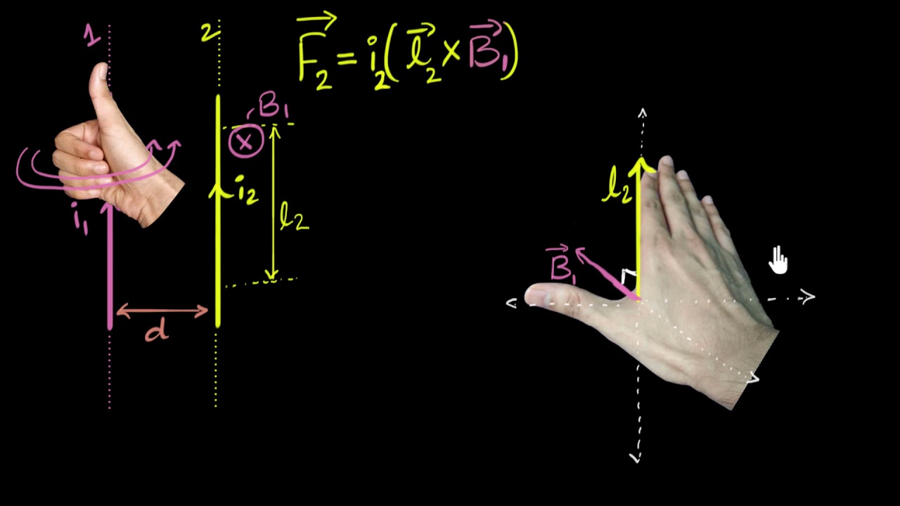
Two current-carrying conductors exert magnetic forces on one another. For an idealized pair of long, straight, parallel conductors in air, force per unit length can be estimated as F/L = 2 × 10^-7 × I1 × I2 / d. Here F/L is newtons per metre, I1 and I2 are instantaneous amperes and d is the centre-to-centre distance in metres. The relationship illustrates the influence of current and separation; it is not a general busbar support design formula.
For example, using equal instantaneous currents of 50,000 A and a separation of 0.10 m gives 5,000 N/m in that idealized two-conductor model. Doubling both currents makes the force four times greater. This hypothetical example omits three-phase geometry, finite bar width, multiple conductors, dynamic response and restraint conditions. It cannot establish a safe span, a support load rating or a product short-circuit declaration.
Check conductor stiffness and orientation
A conductor is also a structural member. Its width, thickness, orientation, temper and operating temperature affect bending behavior. Rotating a flat bar changes the stiffness about the loaded axis without changing its cross-sectional area. Therefore two arrangements with the same copper area and continuous-current duty can behave differently during a fault. Record the actual orientation rather than describing the bar only by area.
Multiple bars per phase introduce additional interactions. Spacers and intermediate restraints control relative movement between sub-conductors, while the main supports restrain the phase group. A calculation for one solid bar cannot automatically represent several thinner bars. The assessment should distinguish the load on the complete group from the load and span of individual sub-conductors, including the forces transferred through spacers.
Follow the force through the entire support chain
A strong insulator is insufficient if its mounting bracket bends or its attachment pulls out. Trace the load from conductor clamps through support bodies, bolts, rails, brackets and the enclosure structure. Confirm the direction in which a published mechanical rating applies and whether it covers the supplied mounting orientation. A tensile rating cannot be used as a bending rating without an appropriate basis.
Material condition also matters. Support temperature, environmental exposure, damage during transport and incorrect tightening can change the installation from the verified arrangement. Ask for identification of the complete support assembly and approved hardware. Mixing a visually similar support body with an unverified clamp or rail can invalidate the original evidence even when the nominal support spacing remains unchanged.
| Masukan Desain | Detail yang diperlukan | Verification question |
|---|---|---|
| Arus gangguan | Peak, duration and protection conditions | Does the evidence cover the specified event? |
| Konduktor | Dimensions, material, temper and orientation | Is stiffness represented correctly? |
| Phase group | Bar count, phase spacing and spacers | Are group and sub-conductor loads covered? |
| Support assembly | Body, clamp, hardware and load direction | Do ratings apply to the supplied configuration? |
| Mounting | Bracket, rail and enclosure attachments | Can the full load reach the frame? |
| Special locations | Bends, ends, joints and equipment interfaces | Are critical restraints included? |
Include bends, joints, ends and device connections
Straight repeated spans are only part of a panel. A bend changes force direction and conductor geometry. An unsupported end can impose a different load on the last restraint. A joint or device terminal may interrupt the ideal beam assumed in a simple calculation. Locate those features on the same drawing used for support assessment so none disappears between the electrical and mechanical design packages.
Do not assume a breaker terminal is an additional structural support unless the manufacturer permits that function. Cable tails and rigid busbar links can transfer loads into equipment that was not intended to carry them. Likewise, moving a joint next to a support may change assembly access, fastener placement or thermal behavior. Resolve those interfaces before freezing the conductor fabrication drawings.
Use verification evidence with matching boundaries
A test report is useful only when it can be linked to the proposed assembly. Review conductor geometry, number of bars, phase spacing, support type, span, frame stiffness and fault conditions. Where a proposed layout differs, the manufacturer must establish whether the allowed verification method covers the change. A smaller dimension is not automatically conservative when it changes stiffness, resonance or load distribution.
IEC TR 60865-2 provides calculation examples associated with the methods in IEC 60865-1. Examples help engineers understand the method but do not supply a universal support schedule. A supplier should identify the assumptions and governing checks used for the specific design, including support reactions, conductor stress and any relevant dynamic effects, rather than quoting a single calculated spacing without its basis.
Review the actual SUTON enclosed assembly
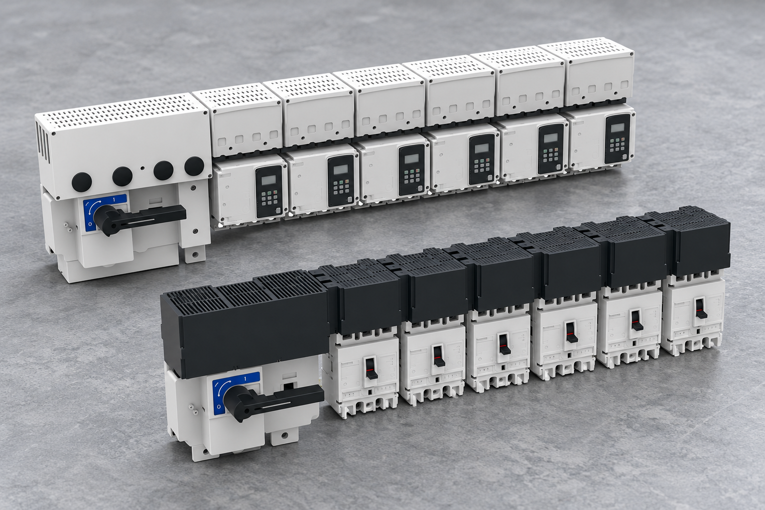
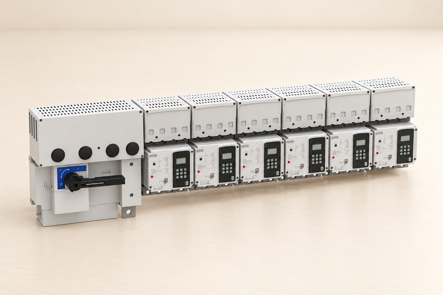
Untuk SUTON ETFZX sistem busbar tertutup, request the order-specific support arrangement and applicable verification information. Exterior product images help identify the family and connection layout. They do not expose internal supports, establish conductor dimensions or prove a particular fault withstand capability. Specify the exact configuration so the requested evidence applies to the equipment being purchased.
Continuous loading remains a separate design check. Use the busbar current-rating guide to define normal duty and the busbar material comparison to frame material questions. A mechanically adequate span does not independently approve operating temperature, and an acceptable temperature-rise result does not independently establish fault-force restraint.
Inspect the installed layout and control changes
At factory inspection, compare the support locations and hardware with the released drawing. Check conductor orientation, unsupported tails, intermediate spacers and attachments that may be obscured after covers are fitted. Record discrepancies before enclosure completion. Photographs should show enough context to locate each support and should accompany dimension records rather than replace them.
During a retrofit, stop treating the original support schedule as automatically valid if the protective device, fault level, bar geometry or connection route changes. Request reassessment using the current arrangement. Retain the approved drawing revision and disposition of any deviation. This gives future maintenance teams a clear boundary between an accepted replacement part and a modification that needs engineering review.
A useful enquiry includes the single-line diagram, fault-study reference, conductor drawing, installation environment and required verification documents. Ask the supplier to state what information is still missing before giving a support schedule. Early clarification is more useful than a confident distance that later proves incompatible with the selected enclosure or protective-device combination. Record which party owns the final assembly verification and which party checks site mounting.
Check the drawing again after shipping splits are joined on site. Transport sections can introduce field joints and temporary restraints that are absent from the final load path. Confirm that permanent supports, brackets and spacers are installed in their specified positions and that temporary shipping pieces are handled as instructed. Record any missing support or mounting substitution as an open deviation; the factory drawing alone does not prove that the assembled installation matches the verified arrangement.
Pertanyaan yang sering diajukan
What is the standard busbar support spacing?
There is no universal spacing for all panels. The permitted span depends on conductor geometry and orientation, phase arrangement, support construction, mounting stiffness and short-circuit duty. Use the verified assembly drawing or a suitable engineering assessment that covers the actual configuration and applicable project requirements.
Can I use breaker interrupting capacity to choose supports?
Not by itself. Breaker interruption and assembly mechanical withstand describe different functions. Establish the fault duty and the protective-device conditions that apply to the complete assembly, then verify the conductors, supports and mounting arrangement against that duty using the appropriate method.
Is adding more supports always acceptable?
No. Extra restraints can change load distribution, thermal expansion behavior, assembly access and insulation paths. They may also require new mounting holes or fasteners. Follow the approved design and obtain the manufacturer's assessment of changes rather than assuming a shorter span automatically preserves every original verification condition.
Video edukasi
Force between two parallel current wires | Moving charges & magnetism | Khan Academy by Khan Academy India – English. This Khan Academy lesson explains forces between parallel current-carrying wires, supporting the simplified force example above. It does not calculate a permitted busbar support span or verify a switchgear design.