SPD lead length affects the voltage that reaches protected equipment because the connecting conductors add impedance during a rapidly changing surge current. A low catalog protection level does not guarantee the same result after long, indirect or looped connections are added. Review the complete path from the supply connection through any backup protective device and the SPD to the protective-earth connection. Keep it short within the approved design, while preserving conductor sizing, clearances and safe access. This guide explains what to measure, how to interpret the effect and what panel buyers should request before accepting a layout.
Distinguish device performance from installed performance
The manufacturer's voltage protection level, Up, is a declared characteristic under specified test conditions. It describes the device being tested. An installation adds conductors, takeoff points, protective devices and connections that are not all represented by the same catalog value.
During a fast surge, the voltage associated with conductor inductance can matter. The relevant relationship is V = L × di/dt: induced voltage equals inductance multiplied by the rate of current change. This is different from evaluating a conductor only by its normal power-frequency resistance or its ability to carry steady current.
The actual equipment-side result depends on the complete circuit and bonding arrangement, so a simple formula is not a full installation simulation. It does explain why shortening an unnecessarily long path can be useful even when the cable has a large cross-sectional area. Conductor area and conductor route solve different parts of the problem.
Measure the complete connection path
Do not measure only the cable leaving the SPD's PE terminal. Identify the supply takeoff, any external backup fuse or breaker, the SPD connection and the relevant protective-earth point. Follow the path defined in the applicable diagram and instructions.
An external protective device can add two conductor segments that are easy to overlook on a schematic. A drawing with adjacent symbols may conceal a long physical route inside the panel. Measure or estimate the actual installed route on the layout, including bends needed for terminals and access.
Keep connection lead length distinct from the distance between the distribution board and the protected equipment. Both can matter, but they are different design questions. A long outgoing circuit does not mean the SPD's own connecting leads are necessarily long, and short SPD leads do not settle every downstream protection requirement.
Use numerical guidance with its stated context
An IET question-and-answer document discussing BS 7671:2018 states a preference for total connecting conductors no longer than 0.5 m, with a 1.0 m upper limit in the cited requirement. That is a specific published reference, not an unconditional current rule for every country, edition or product.
For the actual project, check the adopted installation standard, the relevant edition and the exact SPD manufacturer's instructions. Other arrangements or measures may be described in the applicable rules. Do not treat an old quotation of one clause as a complete assessment of an installation today.
The practical purchasing request is to ask the designer to identify the governing requirement and mark the corresponding connection path on the layout. That creates a measurable acceptance condition and avoids the ambiguous instruction keep wires short without showing which wires are included.
A limited example of the inductive effect
Consider a hypothetical connection segment with an effective inductance of 0.6 microhenry and an assumed current change of 5 kiloamperes per microsecond. Converting the units gives L = 0.6 × 10^-6 H and di/dt = 5 × 10^9 A/s. The relationship V = L × di/dt gives 3,000 V for that assumed segment.
The inputs are illustrative, not measured SUTON values or a guaranteed surge waveform in a real installation. The example shows how a fast current change can create a substantial voltage associated with a connection. It cannot be added casually to every catalog Up value to declare the final equipment voltage.
A real assessment must consider the network, conductor arrangement, current distribution, protection modes and test conditions. Use the calculation to understand the mechanism, then use the approved installation design to make the actual selection and layout decision.
Review layout choices before assembly
| Layout item | Review action | Avoid |
|---|---|---|
| Supply takeoff | Identify the approved connection point | Measuring only the visible SPD tail |
| Bảo vệ dự phòng | Include relevant segments through the external device | Omitting a required device to shorten wiring |
| PE connection | Confirm the correct bonding point and route | Using an unverified nearby metal surface |
| Con đường cáp | Plan direct supported routing and required bends | Unnecessary coils and detours |
| Conductor requirements | Maintain approved size, termination and support | Trading required conductor size for shorter length |
| Phê duyệt | Record actual route and measurement endpoints | An unmeasurable instruction to keep leads short |
This qualitative table supports a physical layout review. It does not authorize changes to protective bonding, terminal assignments or required conductor sizes. Every change must remain within the approved assembly and device instructions.
Start with the supply takeoff and protective-earth point, then position the SPD and any required backup device together where possible. Review the door, barriers, nearby heat sources and access for replacing modules. The shortest sketch is not automatically the best arrangement if it obstructs safe maintenance or violates clearances.
Avoid unnecessary loops and detours
An extra coil of cable left for convenience can create a longer and less favorable surge path. Plan the required length rather than storing excess conductor beside the device. Keep routing direct within the manufacturer's conditions and the panel design.
That does not mean forcing a cable into a sharp bend, placing tension on a terminal or ignoring bend-radius requirements. Cable support and mechanical strain relief still matter. A route must remain electrically suitable, mechanically sound and maintainable after the door closes.
Where several protective stages are present, document the route at each stage. A short connection at the main board does not validate the layout at a remote sub-board. The guide to Type 1, Type 2 and Type 3 coordination covers the wider protection strategy.
Do not solve length by ignoring backup protection
A designer may discover that a separate branch fuse or breaker makes the connection route longer. The response should be to review placement and the approved protection arrangement, not omit a required protective device. Short-circuit coordination remains a separate safety requirement.
If the manufacturer supports use of an existing upstream protective device, document the exact conditions before changing the branch design. A maximum backup rating is not proof that any available breaker qualifies. The article on SPD backup protection sizing explains the necessary evidence.
Likewise, a compact combined SPD assembly may have documented features that simplify installation, but its dimensions alone do not prove better protection. Compare the complete electrical duty, terminal conditions and installed route before selecting it for convenience.
Review the protective-earth connection in context
The SPD's PE path connects into the installation's bonding arrangement. Its purpose cannot be separated from the rest of the electrical system. A nearby unverified metal surface is not automatically a suitable connection point, and a separate local electrode is not a universal solution to a long panel route.
The designer should confirm the connection point and the bonding arrangement, then review the corresponding conductor route. Do not create isolated earth references simply to make a cable shorter. Equipment connected to several services may experience differences in potential between those services during a surge.
The SPD earthing-system selection guide addresses how system identification fits into the selection. This article concerns lead routing after the protective circuit and connection points have been resolved.
Evaluate a retrofit without guessing from photographs
For an existing board, request a safe survey by competent personnel. Collect the SPD code, supply arrangement, upstream protection and a layout showing the actual connection route. A photograph may reveal a long loop, but it cannot establish conductor size, fault duty or whether all sources are isolated.
Compare the current route with the applicable instructions. If a change is needed, have the assembly designer assess moving the SPD, relocating approved branch protection or using another supported arrangement. Record the reason and the revised layout before work begins.
Do not shorten a lead by casually moving it to a different neutral or PE point. That can change the protective circuit or bonding relationships. HSE guidance on working near electricity emphasizes identifying sources and establishing safe isolation; this article does not provide a live rewiring procedure.
Accept the installed arrangement with evidence
At handover, retain the approved drawing and record the actual route that was installed. Where length is an acceptance condition, specify the measurement basis so future reviews use the same endpoints. Note any approved alternative arrangement or manufacturer-specific condition.
Check the terminal identification, conductor requirements and backup device against the schedule. Confirm that maintenance access has not required an undocumented detour. A clean exterior and a healthy indicator do not establish the connection performance.
Changes to a board can alter the route even when the SPD itself remains untouched. Adding a barrier, moving a PE bar or replacing branch protection should trigger a review of the affected path. Keep the layout record current rather than assuming the original commissioning evidence describes every later modification.
Include routing in the SUTON inquiry
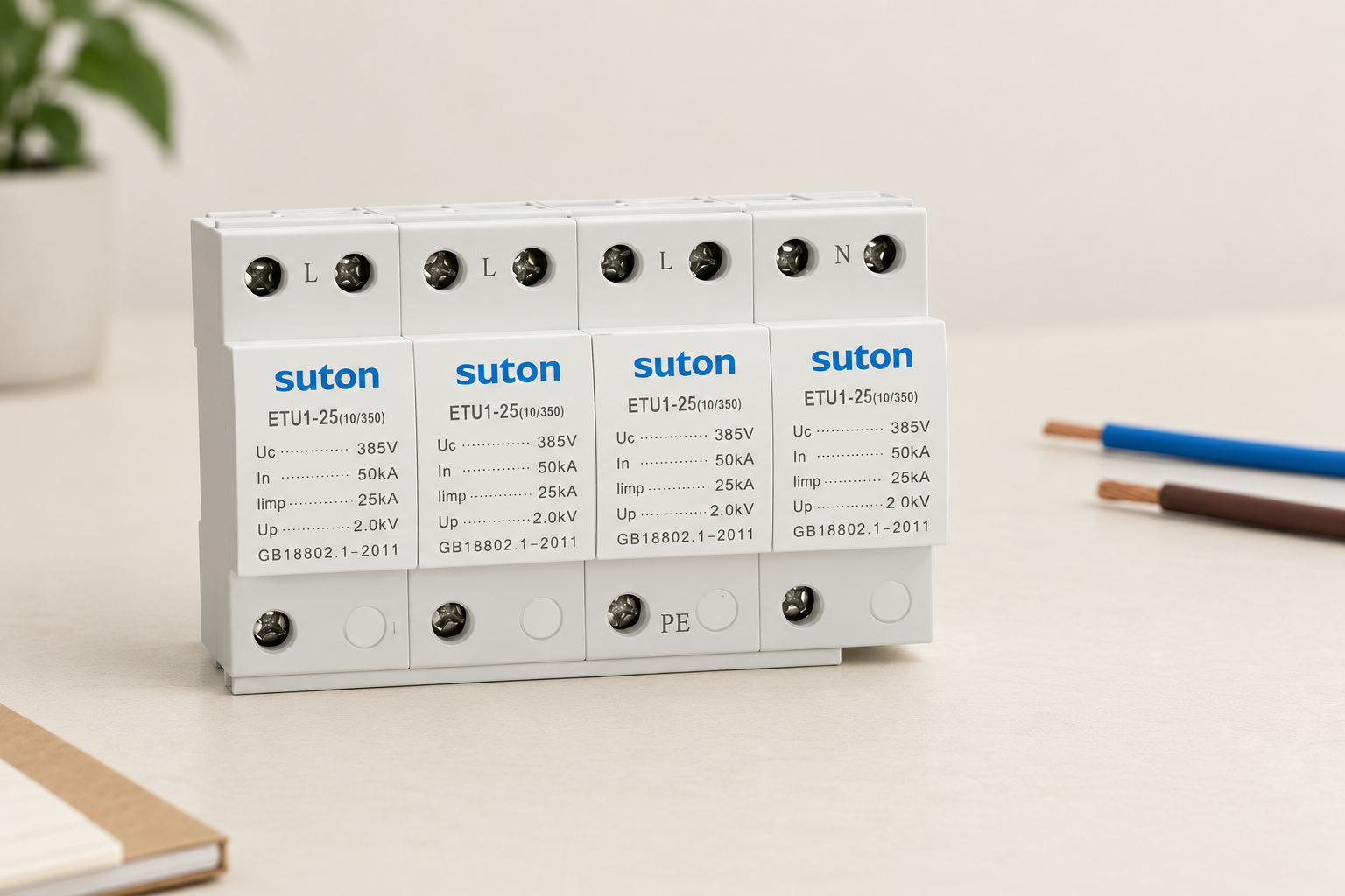
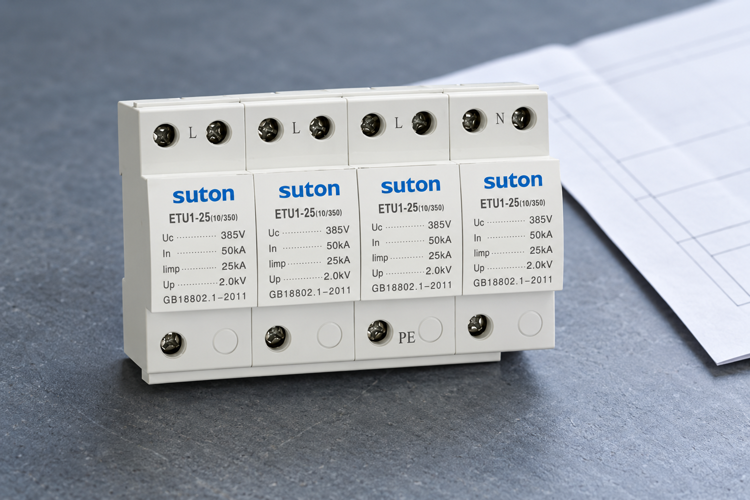
Đối với SUTON ETU1 product family, send the intended panel layout and request the exact model's connection instructions, conductor requirements, terminal limits and backup protection conditions. The family photograph illustrates the exterior, not a validated wiring route.
Compare Lựa chọn SPD loại 2 và Uc, Up, In and Imax ratings before accepting a device. Then assess the actual installation geometry. Keeping product selection and physical connection review together helps prevent a suitable device from being undermined by an avoidable layout problem.
Các câu hỏi thường gặp
Does a larger conductor eliminate the effect of long leads?
No. Conductor size and route length address different characteristics. Follow the required conductor size and keep the approved surge path appropriately short.
Should only the PE lead be measured?
No. Use the complete path and endpoints defined by the applicable instructions, including relevant supply and backup-protection segments.
Can a required backup fuse be removed to shorten the route?
No. Review the layout or a documented alternative protective arrangement. Connection length does not justify omitting required short-circuit protection.
Tham khảo và phạm vi áp dụng
Nền tảng kỹ thuật: IET SPD technical Q&A, Hướng dẫn bảo vệ dòng điện của BEAMA, Hướng dẫn an toàn điện của HSE. Áp dụng các tiêu chuẩn được áp dụng trong dự án và hướng dẫn sản phẩm chính xác. Các hình minh họa sản phẩm thể hiện hình ảnh của gia đình SUTON và không xác định các đánh giá hoặc phê duyệt lắp đặt không được liệt kê.
Video giáo dục
Báo cáo “Chống quá dòng – Các nguyên tắc cơ bản”, do Cơ quan Thực thi Điện lực IAEI thực hiện, cung cấp thông tin giáo dục chung về việc chống quá dòng. Nó không đưa ra các chỉ số đánh giá cụ thể cho từng mô hình và không thay thế thiết kế dự án. Các nội dung thảo luận về khung quy định lắp đặt phải được kiểm tra lại với các quy định được thông qua bởi dự án.