A switch disconnector auxiliary contact rating must be selected for the control circuit it actually switches. The main device's current rating does not establish the auxiliary contact's permitted voltage, load type, switching current or minimum reliable signal level. Begin with the exact accessory code and the connected load, then request the applicable AC or DC duty, terminal information and contact sequence. For a panel purchase, the result should be an approved control diagram supported by the accessory's own data. An auxiliary contact can provide a defined signal, but it is not automatically proof of electrical isolation or absence of voltage.
Describe the signal before selecting the accessory
Identify what the receiving system needs to know. A control drawing may require an open-position signal, a closed-position signal or another explicitly defined mechanical state. Describe that state in words before assigning terminal numbers. Also identify the receiving device: a PLC input, lamp, relay coil or other load. These applications can place different demands on a contact, even when the control supply has the same nominal voltage. A short description such as one auxiliary is therefore insufficient for a reliable quotation.
Keep normal operation, loss of control supply and wiring failure separate in the functional description. An extinguished lamp can result from several conditions and should not be interpreted as an independently verified switch position. The responsible control designer must define how the signal is used and what the system does if it becomes unavailable. Do not silently turn an ordinary indication contact into a safety function because the same signal appears on an operator screen or maintenance checklist.
What the actual HGL page establishes
The SUTON HGL/ETGL load disconnector page states that two sets of auxiliary contacts may be fitted. This supports asking for an auxiliary option on the exact offered model. It does not, by itself, identify the contact arrangement, terminal numbering, operating sequence or the auxiliary circuit's electrical ratings. Request those details with the accessory code and its approved installation instructions. Do not infer a control-circuit rating from the main switch's large current figure.
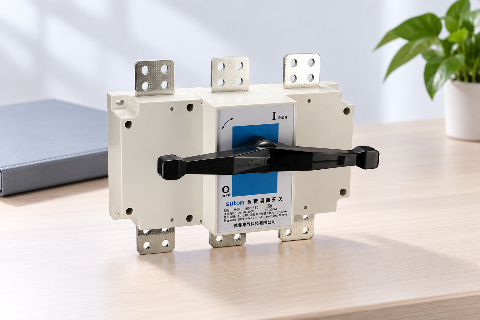
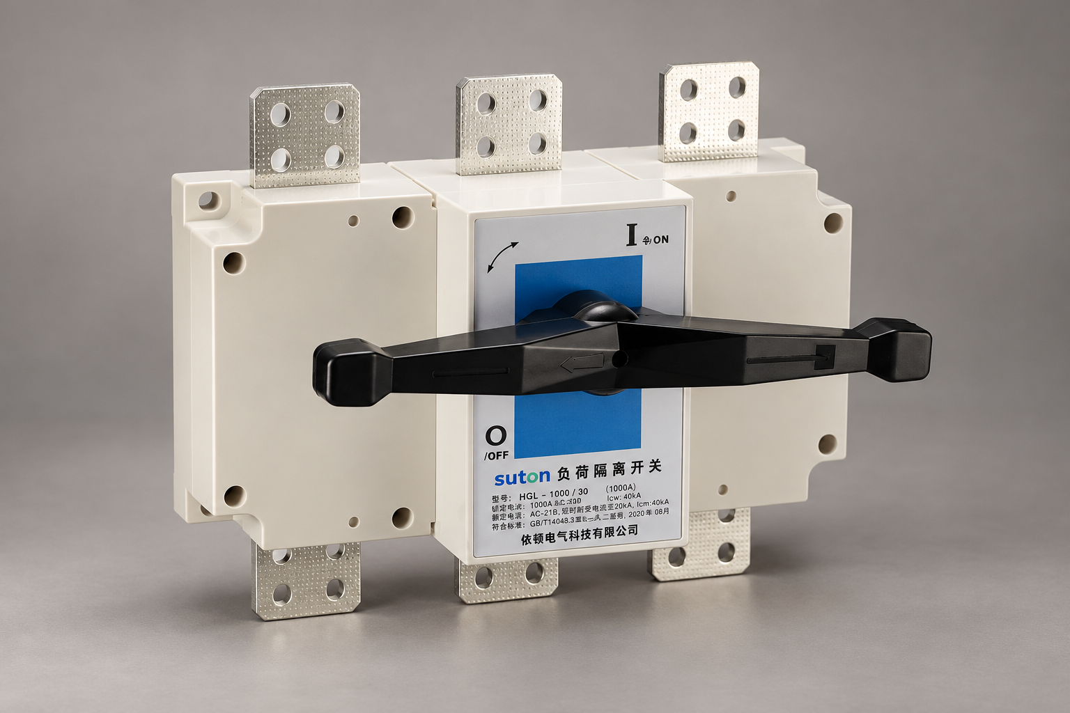
The product description also distinguishes operating functions and limits models rated 1000 A and above to electrical isolation. An auxiliary option does not remove that restriction or give the main device a new switching duty. Equally, an illustration of the external switch cannot confirm which auxiliary module is installed inside or alongside it. Treat the images in this guide as family identification aids. They do not show a verified accessory, contact layout, internal mechanism or control wiring arrangement.
Keep main-circuit and auxiliary-circuit evidence separate
The main circuit carries the power load, while the auxiliary circuit serves the declared control or indication task. Their ratings describe different components and duties. A catalogue's insulation voltage, thermal current or main switching category should not be copied into an auxiliary-contact specification without an explicit declaration covering that contact. Ask the supplier to identify which table belongs to the accessory and which belongs to the parent switch. Preserve the heading and test conditions with every quoted figure.
The Ith and Ie explanation for switch disconnectors helps distinguish thermal and operational current for the main device. Apply the same discipline of retaining conditions when reviewing accessory data, without assuming the two components use identical categories or limits. A large main switch can have a modest indication contact, and a contact suitable for one control load may be unsuitable for another. Selection requires its own evidence rather than proportional scaling from frame size.
Match voltage, current and load behavior together
Identify whether the control supply is AC or DC and obtain the accessory's declared rating for that supply and load. A single current figure without voltage and duty is incomplete. A relay coil's switching behavior differs from a resistive indicator load, while a low-level electronic input may need a contact designed for reliable operation at small signals. The supplier should confirm the intended use from actual load data. Do not assume an AC declaration applies unchanged to DC.
Record relevant load information from the receiving equipment's documentation. This may include normal current, switching demand and specified interface conditions. Where suppression is proposed for a coil, the control designer must review the approved arrangement and its effect on circuit behavior. This guide does not specify a universal suppressor or a wiring modification. Do not add a component solely because it appears in a generic diagram for another relay, control voltage or auxiliary-contact family.
Check low-level signals as carefully as larger loads
A contact's maximum switching rating does not establish its minimum reliable operating conditions. For a PLC input, ask the receiving-equipment supplier for the input requirements and the contact supplier for suitability at that signal level. Include environmental and wiring conditions relevant to the design. A contact that can switch a larger load is not automatically the right interface for a small signal. This question is especially useful when a previous design used a lamp or relay instead of an electronic input.
Do not convert an unresolved interface question into a guessed current value. Record the exact input module, supply and accessory codes, and request a written compatibility response. If an intermediate interface is proposed, assess its own ratings and function through the approved control design. Keep the final diagram and parts list aligned. The aim is a documented signal path that can be built and reviewed, not a collection of individually plausible parts connected by assumptions.
Build a control-duty review table
| Control input | Tài liệu bắt buộc | Avoid this shortcut |
|---|---|---|
| Cung cấp | Actual AC or DC voltage | Transferring an AC rating to DC |
| Tải | Receiving equipment and switching demand | Using main-switch current for the accessory |
| Small signal | Input requirements and contact suitability | Treating maximum duty as minimum reliability |
| Contact state | Diagram and defined reference condition | Guessing terminal states from a symbol |
| Sequence | Declared relation to main mechanism | Assuming early-break or safety functionality |
| Cài đặt | Exact accessory code and instructions | Accepting an unapproved generic module |
| Phê duyệt | Final diagram and acceptance evidence | Treating an indication as proof of isolation |
Use this schedule as a request for evidence, with the HGL option statement and the selected accessory documents as its basis. The IEC 60947-3 public publication page identifies the product-standard scope for switches, disconnectors, switch-disconnectors and fuse-combination units. It does not provide every accessory's control duty. Ask the manufacturer to identify the applicable accessory standard and declaration rather than using a standard's title as proof that an unspecified contact meets a required application.
Define contact sequence and indication limits
Ask what the contact indicates, how it is actuated and which state the diagram uses as its reference. Normally open and normally closed labels need an unambiguous defined condition. For a door-operated assembly, confirm that the declaration covers the actual mechanism. If timing relative to the main poles matters, request the manufacturer's stated sequence and limits. Do not invent early-break or late-make behavior from a drawing that only shows an ordinary auxiliary symbol.
For the wider signal specification, the auxiliary switch inputs guide organizes the information a panel designer should define before wiring. This article focuses on the disconnector accessory's electrical duty. Neither guide establishes that a position signal proves every main pole has opened, that all supplies are isolated or that stored energy has disappeared. Those conclusions require the installation's approved verification process and the relevant equipment evidence.
Preserve safe access and installation evidence
The accessory must be approved for the exact switch and installed according to the manufacturer's instructions. Ask for mounting information, connection requirements and any restrictions imposed by the operating mechanism. Keep control wiring layout and access in the assembly review. A correct contact rating does not validate an improvised mounting bracket, unsupported conductor or modified enclosure. The assembly builder should confirm that the final arrangement retains the intended mechanical operation and electrical separation.
HSE guidance on electrical equipment supports competent selection, installation and maintenance. It is not a permission to inspect an energized assembly or an accessory-specific test instruction. Acceptance work must follow an authorized safe method and the exact product documentation. If a signal behaves unexpectedly, investigate under that process. Do not force the switch mechanism, bridge terminals or bypass an interlock simply to make a screen indication agree with an expected state.
Make quotations and handover records comparable
Send the supplier the complete switch code, proposed accessory, control voltage, receiving load and required signal description. Ask for the contact diagram, AC or DC duty, minimum signal conditions where relevant, terminal instructions and sequence information. Require alternatives to identify any differences explicitly. A quotation that only repeats the parent switch rating leaves the central accessory question unresolved, even if its price and delivery date are attractive.
At handover, retain the approved accessory data, final drawing, parts list and acceptance record. Record substitutions and unresolved restrictions so future maintenance staff can order a compatible replacement. The auxiliary contact guide for breakers offers a related example of separating signal purpose from the power function, but breaker accessory ratings do not transfer to an HGL switch. For this family, obtain model-specific confirmation from SUTON and keep it with the actual panel documentation. Use the isolator switch selection guide to connect this accessory review with the complete device selection.
Các câu hỏi thường gặp
Can the main switch current be used as the auxiliary rating?
No. The auxiliary contact belongs to a separate control circuit with its own electrical duty and conditions. Obtain the exact accessory's voltage, current, load category and connection information. The parent switch's frame size or thermal current does not establish those values.
Is a contact with a high maximum rating always suitable for a PLC input?
No. Small signals require consideration of the input requirements and the contact's declared low-level suitability. Ask the two equipment suppliers to confirm the interface using exact part codes and operating conditions. A maximum switching figure alone does not establish reliable operation at a much smaller signal level.
Does an open-position signal prove safe isolation?
No. It is a signal with a defined mechanical and electrical scope. It does not independently identify every supply, prove every conductor is de-energized or replace the site's approved isolation and verification process. Use it only for the function supported by the exact device and control design.
Video giáo dục
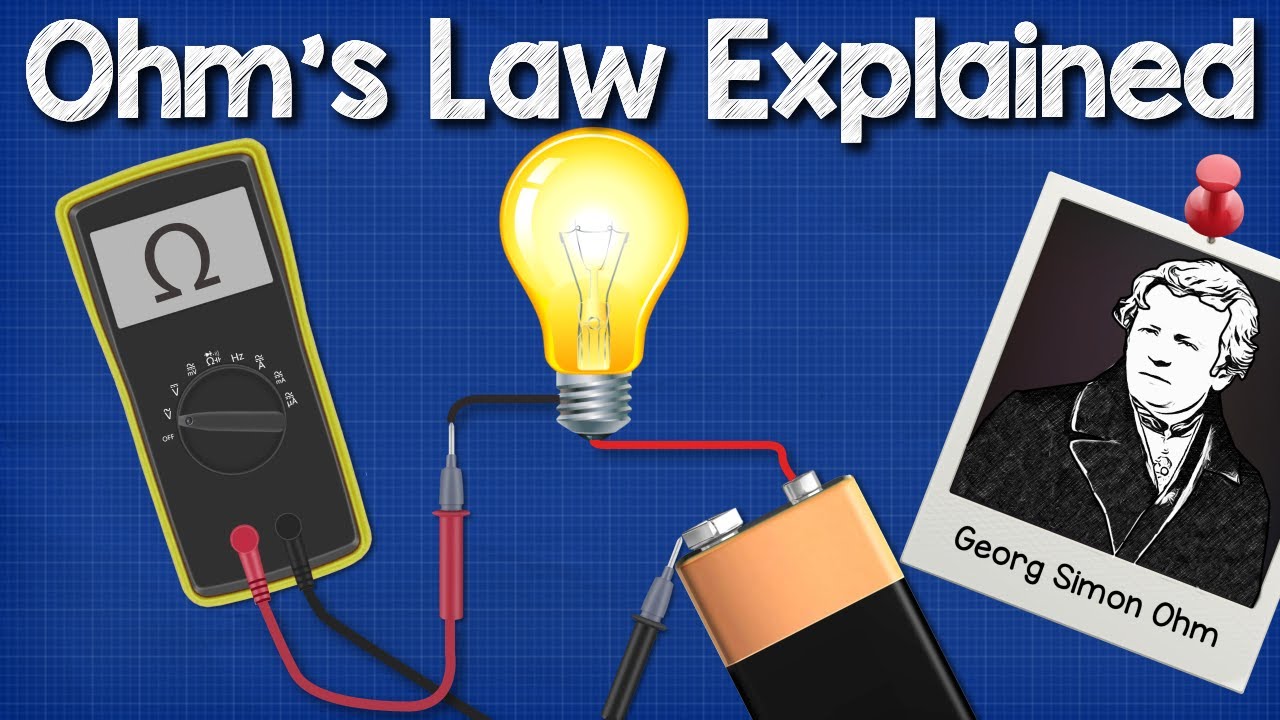
Ohms Law Explained – The basics circuit theory by The Engineering Mindset. Independent education on voltage, current and resistance supports identifying the control-load inputs. It does not declare accessory ratings, contact sequence or PLC compatibility.