PV DC breaker isolation and lockout require more than moving a handle to OFF. First confirm that the exact device has the required declared isolation function and is suitable for the circuit's voltage, configuration and switching duty. Then apply a site-specific electrical safety procedure that identifies every energy source, controls re-energization and verifies the intended work area. PV conductors can remain energized in daylight even when an inverter is stopped. A lockable handle, a disconnected AC supply or a dark display does not independently prove that the equipment to be worked on is de-energized.
Define the work boundary before selecting a disconnect
A PV installation contains several possible work areas: string circuits, combiner sections, inverter inputs, AC connections and storage equipment where present. Mark the actual maintenance boundary on the current diagram. Identify which conductors and components are inside it and which may remain energized outside it. The required isolation points follow from that boundary. A convenient nearby breaker may not disconnect every source that can reach the equipment involved in the task.
For procurement, describe the intended maintenance function before asking for a device. State whether the project needs overcurrent protection, a declared isolation function, operational switching or a combination. The equipment documents should establish each required duty. If the installation requires visible separation, remote operation or a particular lock arrangement, identify that explicitly. Do not expect an ordinary product-family name or an accessory photograph to answer a maintenance safety requirement that has not been defined.
Distinguish breaking, isolation and lockout
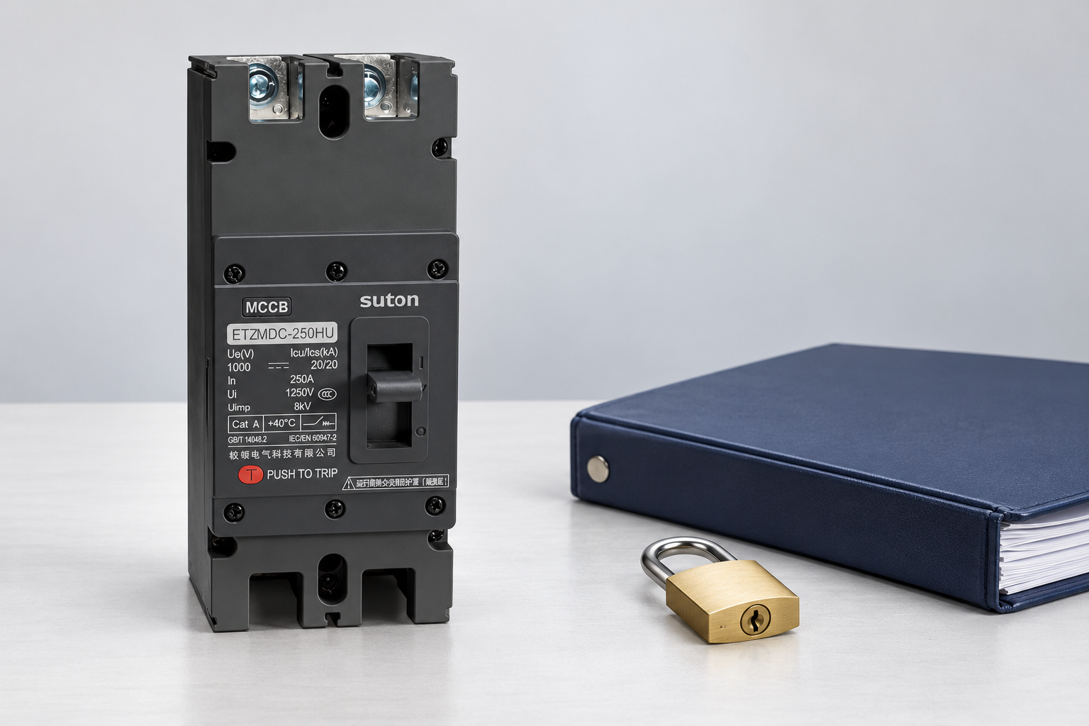
A circuit breaker can provide automatic interruption under defined conditions. Isolation is a separate declared function concerned with the required separation for the application. Lockout is part of the work procedure that controls operation of the relevant isolating means. A device may support several of these functions, but one label does not prove all of them. In particular, fitting a padlock accessory cannot create an isolation rating that the underlying device does not possess.
Ask for the exact model's applicable declaration, instructions and permitted accessories. Confirm whether the device is approved to operate at the expected DC load and how its position indication is defined. If a manufacturer's document covers a switch-disconnector rather than a breaker, do not transfer its claims to a different product. The IET discussion of PV DC switch-disconnector selection provides useful context for that distinction, while the chosen equipment still needs its own evidence.
Identify all sources that can energize the boundary
Document array inputs, parallel sources, storage, AC supplies, auxiliary circuits and stored energy where relevant to the equipment. Follow the inverter and system instructions when identifying energy that may remain after normal operation stops. Do not assume that the direction of ordinary power export describes every energization path. Changes to an inverter, battery or combiner can alter the isolation plan, so the work procedure and drawings must stay aligned with the installed system.
PV modules can produce voltage when illuminated. Stopping the inverter does not make all array-side conductors safe to touch. Similarly, disconnecting the AC side does not by itself isolate the DC array. The safety procedure should clearly distinguish equipment that can be de-energized for the task from portions that remain energized and require controls. An article cannot determine the safe work boundary for an unseen site; that assessment belongs to qualified personnel using the actual installation information.
Specify the device and accessory evidence
Use the accepted maximum DC voltage and configuration, design current, available fault duty and environmental conditions when reviewing a proposed device. The solar PV DC breaker selection guide covers the broader electrical purchase checks. For isolation, add the declared function, permitted operating duty, required conductor switching and accessory compatibility. A suitable electrical current rating alone does not answer whether the device can perform the intended maintenance isolation role.
Locking accessories must fit the exact device and the site's control procedure. Ask whether the accessory locks the relevant mechanism in the required position, how it is installed and what restrictions apply. Check access in the proposed enclosure and whether covers or nearby cables obstruct its use. Do not improvise a locking method from tape, an unrelated clip or an accessory intended for another model. Retain the approved accessory order code with the breaker schedule.
Use a maintenance isolation planning sheet
| Planning item | Evidence or decision | Câu hỏi ôn tập |
|---|---|---|
| Work boundary | Current diagram and task description | Which parts must be made safe for this task? |
| Energy sources | Array, storage, AC, auxiliary and stored-energy review | Can another path energize the boundary? |
| Device function | Exact model isolation and switching declarations | Does the device provide the required duty? |
| Operating controls | Approved locking accessory and site procedure | Can unauthorized re-energization be controlled? |
| Xác minh | Qualified procedure and appropriate instruments | How is the intended work area verified? |
| Residual hazards | Parts remaining energized and associated controls | Are boundaries and access understood? |
| Phục hồi | Authorized inspection and release process | Are drawings and records current after changes? |
This planning sheet organizes the questions; it is not a step-by-step authorization to work on energized PV equipment. The employer or responsible organization must establish the actual procedure and the competence required. Unanswered source or boundary questions should be resolved before work begins. A checklist signed without current drawings and equipment identity cannot compensate for a misunderstood circuit, so give the reviewer access to the evidence behind every critical entry.
Verify the work area through the approved procedure
Verification must address the actual conductors and parts involved in the task using appropriate instruments and the site's established method. A handle position and an inverter display provide information, but neither replaces the required verification. Follow the applicable rules for instrument suitability and checking its operation. Equipment that can be re-energized from another source requires controls addressing that possibility. Do not rely on a remembered installation layout when the current drawing or physical arrangement differs.
For U.S. general-industry electrical work, OSHA's electrical safety requirements, reproduced by Cornell LII provide a relevant regulatory starting point for de-energization, controls and verification. Their applicability must be considered for the actual workplace, and other jurisdictions have their own requirements. This article does not replace those rules or a site procedure. The important procurement lesson is that equipment capability and work-process controls must support each other rather than being treated as interchangeable protections.
Đánh giá các bằng chứng về sản phẩm SUTON thực tế
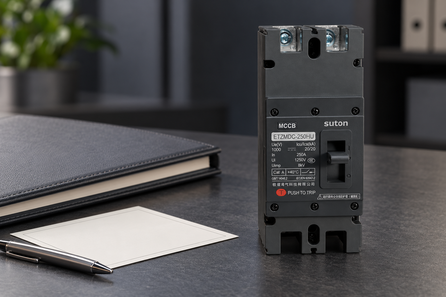
The SUTON ETZM PV molded-case DC circuit breaker is a relevant product family to include in a PV protection enquiry. The reference images show its actual exterior for identification. They do not certify an isolation function, prove a lockout accessory is available or establish how any particular model indicates contact position. Request written model-specific information addressing the intended application before selecting it for a maintenance boundary.
Provide the circuit diagram, maximum voltage, arrangement and environmental conditions with the enquiry. Ask the supplier to distinguish the breaker's protective function from any declared isolation or switching function. Request the approved locking accessory and installation instructions if available and required. Where the proposed product does not provide the complete function, the system designer should specify suitable additional equipment rather than assigning an unsupported duty to the breaker merely because its handle can be moved to OFF.
Treat connectors and covers as separate issues
Opening a PV connector under load is not a substitute for using suitable switching equipment. Likewise, removing a cover does not establish isolation and may expose energized parts. The procedure should address access, residual hazards and the condition of the work area. Do not create a live demonstration by unplugging connectors or deliberately causing an arc. Those actions can introduce severe hazards without proving that the selected isolation arrangement is suitable.
The national laboratory overview of PV DC systems and safety provides wider context on PV-specific hazards. Use it alongside the actual equipment manuals and applicable requirements. If a device, connection or enclosure shows heat or arc damage, follow the site's response process and have qualified personnel investigate. A successful reset or a normal-looking handle does not independently establish that equipment is suitable to return to service after an abnormal event.
Keep restoration and future changes controlled
The work procedure should include inspection, removal of temporary controls and restoration through the site's authorized process. Maintain equipment identity, approved diagrams and records of changes made during maintenance. If the breaker or accessory is replaced, verify that the new combination preserves every required function. An electrically similar alternative can have different locking arrangements, indications, terminals or operating restrictions, so the original maintenance instructions may need review before the equipment returns to normal service.
Future additions also require attention. Adding strings, changing an inverter or connecting storage can introduce new energization paths that the original isolation plan did not cover. Link the maintenance record to the latest drawings and protection schedule. The guide to PV MCCB selection helps structure replacement enquiries, while DC breaker polarity addresses direction limitations. Review those equipment details alongside the work boundary rather than assuming the old lockout arrangement remains complete.
Các câu hỏi thường gặp
Does moving the PV breaker to OFF make the whole installation safe?
No. Identify the actual work boundary and every source that can energize it, then follow the applicable isolation, control and verification procedure. Array-side conductors can remain energized when illuminated, and storage, auxiliary supplies or other paths may need separate controls. Handle position alone is insufficient evidence.
Does a padlock accessory prove that a breaker is an isolator?
No. Confirm the exact device's declared isolation function and the approved accessory separately. A locking accessory supports an operating-control procedure but cannot create an electrical capability that the underlying device lacks. Verify model compatibility and the intended locking position using current instructions.
Can the AC inverter disconnect replace DC isolation?
Do not assume that it can. Disconnecting AC does not necessarily remove PV DC voltage from the work area. Qualified personnel must identify the required isolation points from the actual diagram, equipment instructions and task boundary, then verify the intended work area under the site's procedure.
Video giáo dục
How do solar panels work? – Richard Komp by TED-Ed. This independent TED-Ed lesson explains how photovoltaic cells generate electricity. It supports the PV-source context; it does not approve breaker wiring, sizing, thermal limits or a maintenance isolation procedure.