Select a DC circuit breaker for solar PV by checking the maximum corrected array voltage, required circuit current, available fault current, approved pole arrangement and the conditions inside its enclosure. The breaker must be documented for the particular DC duty and wiring configuration. An AC rating, a similar case size or a convenient current value is insufficient. First identify whether protection belongs at a string, combiner output or another circuit boundary. Then coordinate the device with module limits, conductors, inverter requirements and the installation rules applicable to the project.
Identify the circuit before choosing a breaker
A PV string circuit, a combined array output and a battery circuit are different applications. They can have different sources of fault current and different interruption duties. Mark the proposed breaker on the single-line diagram and identify every source that can feed a fault at that location. Include parallel strings, inverter contributions where applicable and any connected storage system. A component selected for one location should not automatically be copied throughout the installation.
Whether each string needs overcurrent protection depends on the system configuration, possible reverse current, module limits and applicable installation rules. Do not prescribe a breaker on every string without that analysis. Conversely, a small normal operating current does not prove that protection is unnecessary when other parallel strings can feed a fault. Ask the designer to document the decision so procurement is not forced to guess from panel wattage.
The Department of Energy's inverter explanation distinguishes the DC generation side from the AC interface. Keep that distinction on drawings and schedules. A grid-side AC breaker specification cannot be used as the array-side DC specification merely because both devices belong to the same solar installation.
Calculate maximum voltage from the cold array condition
Begin with the module open-circuit voltage, the number of modules in series and the temperature correction method required for the project. For conventional crystalline-silicon modules, open-circuit voltage generally increases as temperature falls. The array may therefore exceed its normal operating voltage on a cold morning, particularly when the inverter is not drawing power. Nominal system labels and inverter MPPT operating voltage are not substitutes for this maximum-voltage calculation.
Record the module model, datasheet revision, temperature coefficient and design temperature. Apply the module instructions and installation rules, including required tolerances and factors. Then compare the resulting voltage with the breaker's rated operational DC voltage for the exact pole arrangement. The same check must cover cables, connectors, isolators, surge-protection devices and the inverter's maximum input voltage; the lowest applicable limit controls the design.
Do not add individual pole markings arithmetically unless the manufacturer explicitly approves that series connection. Arc interruption depends on internal construction and the specified current path. The site's DC switch-disconnector guide provides a separate switching discussion. It should support coordination, not serve as proof that every switching device provides the same overcurrent protection.
Size current protection without applying a universal multiplier
Use module short-circuit current and the applicable design method to establish the circuit current used for protection and conductor sizing. Consider parallel strings, operating conditions, installation rules and any additional generation effects covered by the module documentation. Do not select the breaker from module watts divided by a nominal voltage. That shortcut can conceal the relevant current and the distinct maximum-voltage requirement.
Coordinate the protective device with the module's permitted series overcurrent protection, conductor ampacity after correction and terminal limitations. The required rated current must remain suitable at the actual enclosure temperature. Applying a familiar factor from another jurisdiction or code edition can produce a misleading answer, so identify the governing rule rather than presenting one multiplier as universal for every PV installation.
Suppose a design worksheet identifies a required circuit current after the applicable factors. That is only the starting point for choosing a standard device size. The designer must still verify thermal derating, cable protection and the upper limits of the connected equipment. Increasing the breaker current to prevent nuisance tripping can remove necessary protection if these checks are skipped.
Check the interruption duty and fault sources
Rated current and breaking capacity answer different questions. The former concerns continuous operation and the protective characteristic; the latter concerns interruption under specified fault conditions. Obtain the available fault-current assessment at the device location. Match it to the applicable DC breaking-capacity declaration at the required voltage and wiring configuration. A high AC breaking-capacity number on related equipment does not establish DC performance.
PV faults can be current-limited while still presenting persistent arcing hazards. If storage is connected, the fault-current magnitude and direction can change substantially. Review the actual topology, including converter behavior and any manufacturer-stated contribution. Keep fault studies separate from the normal generation forecast: annual energy yield does not determine the protective device's interruption duty.
For equipment evaluated under IEC 60947-2, understand what the particular declared breaking-capacity quantities mean in the project specification. For other markets, use the required listing and installation framework. Do not combine a value taken from one standard with an acceptance assumption taken from another. Request a model-specific certificate and supporting data rather than relying on the certification logo visible in a photograph.
Verify pole wiring, polarity and isolation requirements
Some DC breakers require a defined polarity and source/load connection; others have documented non-polarized arrangements. Read the circuit diagram for the exact model. A product family's general description cannot override terminal markings or installation instructions. Where current can reverse, require explicit confirmation that the proposed operating conditions are supported. Never resolve uncertainty by guessing from the physical position of the handle.
Pole count alone does not define the permitted system voltage or grounding arrangement. The instructions may specify series connections, conductor routing and restrictions for grounded or ungrounded systems. Use only approved links and diagrams. A breaker can also have a different isolation function from a dedicated disconnector, so confirm whether the selected device provides the required means of isolation in that installation.
Keep overcurrent protection, isolation, rapid shutdown, earth-fault detection and arc-fault functions distinct. One device does not automatically provide all of them. DOE's solar fire-safety overview provides context for system-level safety responsibilities. The final design must use the locally adopted requirements and qualified installation procedures, rather than treating a breaker purchase as a complete safety solution.
Compare supplier evidence using a purchase checklist
| Selection check | Đầu vào dự án | Supplier evidence |
|---|---|---|
| Điện áp | Maximum corrected array voltage | DC operational rating for the exact arrangement |
| Hiện tại | Required design current and protection limits | Trip characteristic and usable current |
| Dòng cắt sự cố | Available fault sources and current | Applicable DC breaking-capacity declaration |
| Poles and polarity | Grounding, source direction and circuit diagram | Approved terminal and series-link diagram |
| Nhiệt độ | Air temperature at the device and enclosure layout | Applicable derating instructions |
| Kết nối | Conductor size, material and available space | Terminal accessories and tightening instructions |
| Compliance | Required market and project standards | Exact-model documentation and certificates |
Use this checklist to compare complete offers. A lower unit price is not directly comparable when one offer excludes required accessories, suitable terminals or the enclosure arrangement covered by its evidence. Ask the supplier to identify every assumption and exception. Resolve them before purchase, with the final diagram and device reference linked to the approved submittal.
Review the actual SUTON PV molded-case breaker
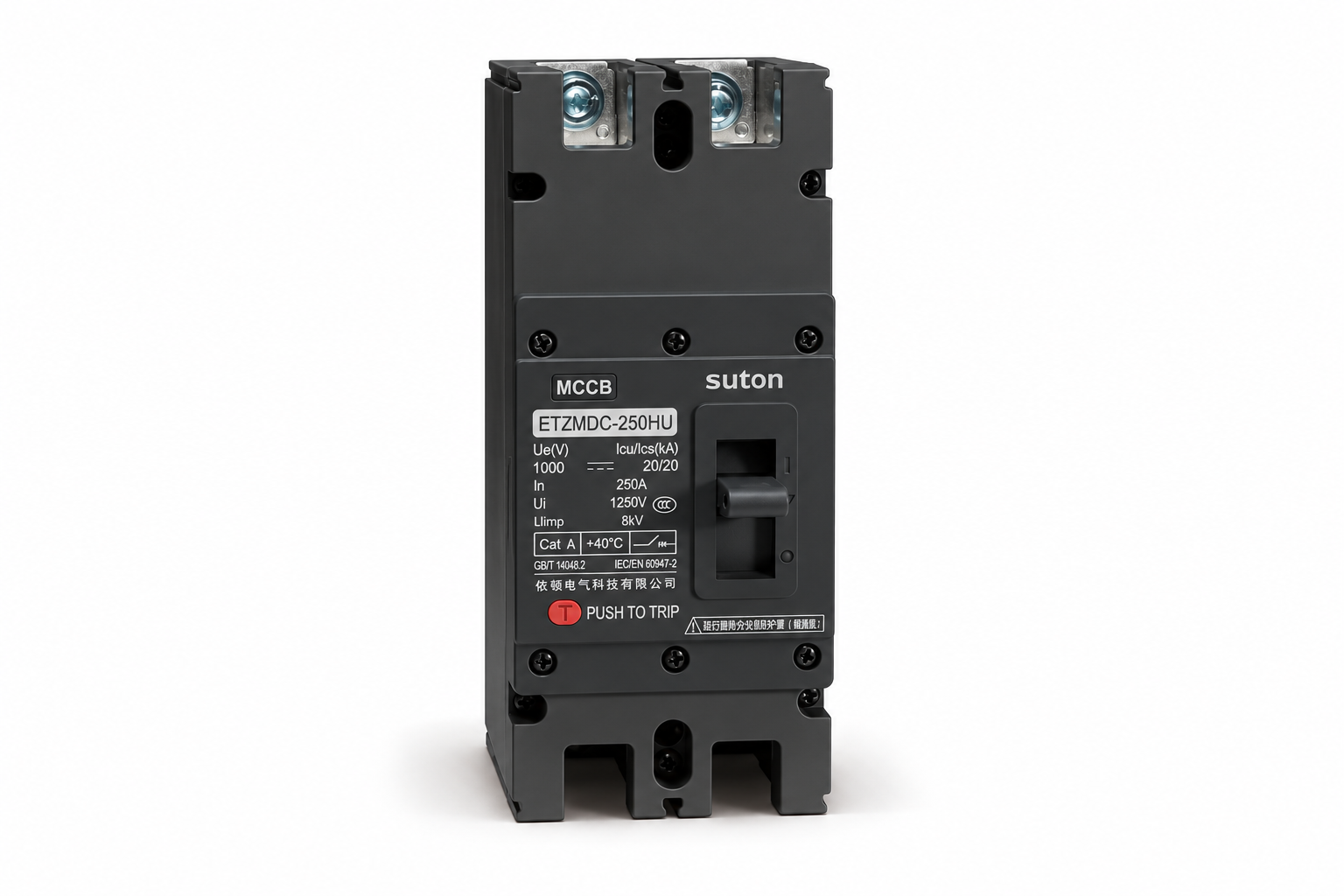
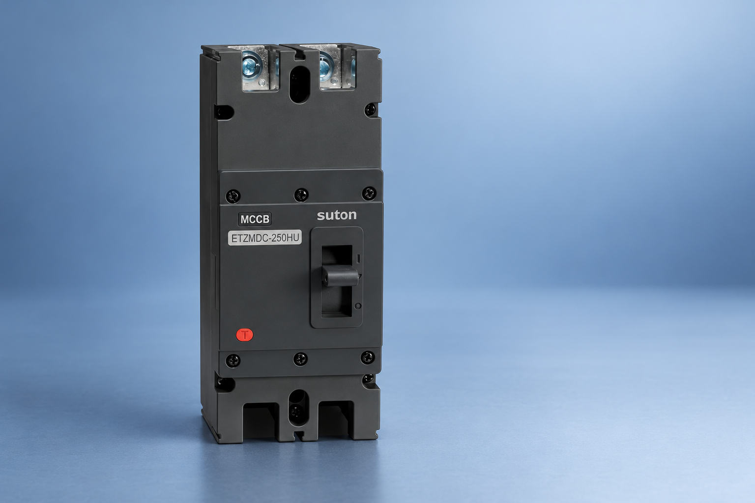
The SUTON ETZM PV molded-case DC circuit breaker is a product reference for discussing an industrial PV protection proposal. Its exterior identifies the molded case, operating handle and connection areas. The illustration does not independently verify voltage, breaking capacity, pole arrangement, polarity, temperature correction or certification. Request the current datasheet and instructions for the precise model being quoted.
Send the supplier a completed circuit schedule rather than asking only for a solar breaker price. State the corrected maximum voltage, circuit current, available fault duty, grounding arrangement, operating temperature, conductor sizes and required approvals. Request the exact terminal diagram and all limitations. If an alternative model is proposed, compare the entire evidence package instead of accepting a matching nominal current as equivalence.
Coordinate the purchase with the site's PV surge-protection selection guide và RCCB selection for PV inverters. These devices address different risks and locations. A surge protective device does not replace overcurrent protection, and residual-current protection on the inverter side does not make an unsuitable array breaker acceptable.
Account for enclosure temperature and connection details
Combiner boxes can run hotter than the surrounding air. Solar exposure, enclosure construction, adjacent equipment and internal losses influence the device environment. Obtain the manufacturer's derating information for the installed arrangement. Verify that the resulting usable current remains compatible with the design and conductor protection. Do not assume an outdoor ambient forecast is the same as the air temperature around the breaker.
Check conductor material, cross-section range, terminal accessories, bending space and specified tightening procedure. A suitable electrical rating can still lead to a poor installation if the selected enclosure prevents correct cable routing or terminal access. Photograph terminal identification and retain torque records where required. Do not use generated illustrations as connection instructions; they show product identity, while installation must follow verified documentation.
Commission and maintain the protection arrangement
Before energization, compare installed model references and links with the approved diagram. Qualified personnel should verify polarity, grounding arrangements, protective settings where adjustable, labels and the completed isolation procedure. PV circuits may remain energized whenever illuminated, even when the AC supply is disconnected. Plan testing and maintenance around all energy sources and use appropriate rated instruments and procedures.
Record the device model, serial details where available, settings, wiring drawing, acceptance checks and maintenance instructions. After a fault operation, investigate the cause and follow the manufacturer's inspection or replacement procedure. Repeated resetting is not diagnosis. Keep substitutions controlled so that a later replacement does not change the approved voltage arrangement, interruption capability or protective behavior.
Các câu hỏi thường gặp
Can an AC circuit breaker be used on a solar DC array?
Only when the manufacturer explicitly documents a suitable DC application, voltage and connection arrangement for that exact device, and the project permits it. An AC marking alone is insufficient because DC interruption conditions differ. Obtain the model-specific instructions and required compliance evidence before selection.
Is panel wattage enough to choose the DC breaker size?
No. Selection requires maximum corrected open-circuit voltage, the applicable current calculation, parallel-source fault contributions, conductor protection, module overcurrent limits and environmental corrections. Panel wattage does not capture these independent requirements or establish breaking capacity.
What information should accompany a PV breaker inquiry?
Provide the circuit location, single-line diagram, module data, series and parallel configuration, corrected maximum voltage, design current, available fault duty, grounding arrangement and enclosure temperature. Add conductor details, required standards and approvals, and request an exact model with its approved wiring and derating instructions.
Video giáo dục
How do solar panels work? – Richard Komp by TED-Ed. This TED-Ed lesson explains how photovoltaic cells generate electrical energy. It supports the PV-source discussion, not breaker sizing or installation approval.