SPD remote signaling contacts allow a monitoring system to receive a condition signal from a surge protective device without placing the monitoring input in the main surge-current path. They typically report a defined device condition rather than measuring how much protection remains. Before connecting one, confirm the exact terminal diagram, contact ratings, normal state and meaning of an alarm. A cabinet drawing that merely says “SPD healthy” leaves too much unexplained for reliable maintenance.
For panel builders and facility engineers, the useful question is how the complete alarm chain behaves when the SPD changes condition, a signal cable breaks, or the monitoring controller loses power. This guide explains how to specify that chain without assuming that every SPD has the same remote-contact option or that a clear alarm proves the installation remains protected.
Separate status indication from protection performance
The surge-limiting elements and the remote indication circuit perform different jobs. The first limits transient voltage under its declared conditions. The second provides information about a condition that the manufacturer has chosen to monitor. A remote contact might follow a thermal disconnector, module presence, a mechanical indicator or another internal mechanism. Only the exact documentation can establish which event it detects.
Do not translate “normal contact state” into an unrestricted claim of complete surge protection. The signal does not ordinarily establish the installed voltage protection level, the condition of the bonding route, the suitability of backup protection or the remaining service life of every internal component. A wrong model can display its normal state while still being unsuitable for the installation.
The Hướng dẫn bảo vệ dòng điện của BEAMA explains the importance of selecting and installing the complete protective arrangement. Use its system-level framework alongside the particular product manual. The remote indication should support that arrangement, with a documented response when the indication changes.
Identify the exact contact option before ordering
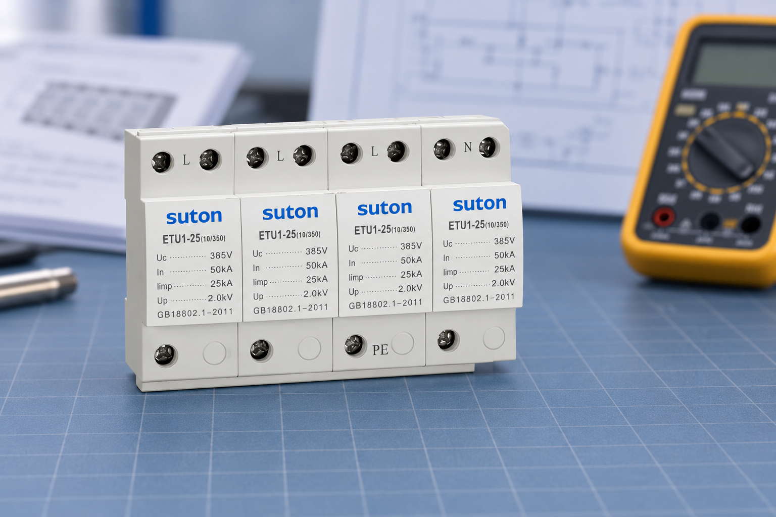
Start with the complete SPD base and module references. Determine whether the remote contact is integral, optional, supplied on a particular base, or unavailable on the ordered version. Similar housings can carry different features. A photograph showing only the front label cannot establish the terminal function or the presence of a signaling accessory.
Ask for a connection drawing that identifies common, normally open and normally closed terminals where applicable. Labels such as C, NO and NC must be interpreted under the manufacturer's stated reference condition. Establish whether “normal” means a healthy fitted module, the unactuated mechanism, or a state shown with no module present. These conditions are not automatically equivalent.
Record the contact's permitted switching voltage and current, minimum load where specified, insulation conditions and allowed wire size. The electrical rating of the SPD's power circuit does not apply to its signal contact. A remote contact intended for a low-energy monitoring input must not be assumed suitable for directly switching a contactor, lamp or alarm sounder.
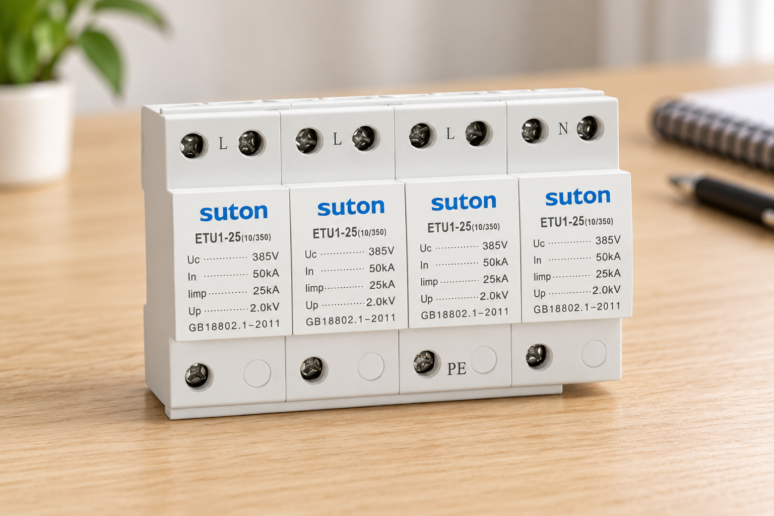
The SUTON ETU1 product family provides the product context for this discussion. Request written confirmation of the exact remote-contact version and terminal drawing before specifying it. The product illustration used here shows external appearance; it does not prove that the pictured version includes a signaling contact.
Design the monitoring input as a separate circuit
Identify the controller's input type before choosing the contact arrangement. A digital input may require a supply referenced to the controller common, a potential-free loop or a particular wetting current. Obtain that information from the controller documentation and compare it with the contact specification. The SPD contact is only one part of the interface.
Keep the monitoring supply and signal wiring within their own documented limits. Where interface isolation is required, specify the appropriate interface and its verified arrangement. Do not bridge incompatible reference systems simply because the contact is described as potential-free. Electrical separation, segregation and enclosure requirements depend on the actual circuit and the rules adopted by the project.
Review how the signal cable enters and crosses the cabinet. Arrange wiring so that identification, maintenance access and required separation are preserved. An alarm cable routed beside a surge-current connection deserves attention because transient coupling can affect the monitoring system. The final routing should be reviewed with the panel designer, not inferred from a generic internet diagram.
Decide what a broken wire should mean
A simple unsupervised contact loop has limitations. If the contact closes only on fault, an open cable can resemble a healthy condition. If it opens on fault, a broken cable can produce an alarm, but a shorted cable may still conceal a device change. The preferred choice depends on how the monitoring system supervises the circuit and which failures matter most.
Define the normal input state, fault input state and controller response in a cause-and-effect schedule. If the controller supports line supervision, use the controller's approved method and components. Do not invent an end-of-line resistor value or assume the SPD manufacturer has approved every supervision arrangement. Check contact load compatibility with the resulting circuit.
Also define loss of monitoring power. A controller that is offline may show the last recorded SPD condition on a dashboard. That stale indication must not appear as a current healthy signal. Include communication-loss handling and a time stamp in the monitoring design when those functions are available.
Build a clear alarm decision table
The following table is a commissioning framework, not a universal terminal diagram. Populate its actual states from the exact SPD and monitoring-system instructions. It separates equipment condition, signal-circuit behavior and the maintenance action so that the operator can understand what the alarm establishes.
| Observed condition | Cần xác minh những gì | Required response |
|---|---|---|
| Normal indication | Exact reference state and current monitoring timestamp | Record the observed state without claiming full surge performance |
| Device fault alarm | Local indication and manufacturer interpretation | Arrange the specified qualified inspection |
| Open signal cable | Controller supervision and accepted loop logic | Identify cable fault separately where supported |
| Shorted signal cable | Whether supervision can detect the failure | Record limitations and repair the signal circuit |
| Monitoring power loss | Controller availability and stale data behavior | Show unavailable status instead of an old healthy state |
For a multi-device cabinet, decide whether each SPD receives an individual input or several contacts form a shared alarm. A shared loop can reduce input count but hides which unit changed condition. If a combined alarm is accepted, label the affected equipment group and provide a local inspection procedure. Do not present a shared input as independent status for every SPD.
Commission the complete signal chain
Commissioning should verify the input state, controller logic, alarm text and actual recipient or display. It is insufficient to see a continuity change at a loose contact while the installed monitoring input remains untested. Save the exact configuration and the evidence that the signal reached the expected destination.
Use only the manufacturer's permitted method to simulate or initiate the indication change. Some devices provide an approved test procedure; others require a controlled module operation under specified conditions. Never remove or manipulate an energized SPD simply to create an alarm. Qualified personnel must determine isolation requirements and follow the instructions for the exact assembly.
A separate signal-circuit test can prove the controller response without claiming to test the SPD's surge performance. If a technician opens a monitoring loop at an approved point, record that the test checks loop handling and alarm logic. It does not establish the condition of the surge-limiting element. This distinction prevents a commissioning report from overstating its evidence.
Đánh giá safe work near electrical equipment before inspection or testing. A monitoring contact does not make adjacent power terminals safe to touch. The activity should be planned around the energized parts, sources and isolation method that actually exist in the cabinet.
Set an actionable maintenance response
An alarm should identify a device or equipment group, location, observed condition and responsible maintenance route. “Surge alarm” alone gives an operator little useful information. Prefer a description tied to the cabinet reference and the manufacturer's interpretation, with instructions for a qualified person to assess the device and protective arrangement.
Define whether the event requires immediate review, a planned replacement or escalation under site procedures. That decision depends on the service, redundancy, exposure and manufacturer's instructions. Do not promise continued operation after a fault indication merely because normal load power remains available. Load availability and transient protection are separate outcomes.
Maintain records of the first alarm, inspection, replacement and restored indication. If the alarm repeatedly returns, investigate supply abnormalities, model suitability, installation conditions and relevant events. Replacing a module without examining repeated failures can conceal a system problem and makes subsequent maintenance harder to interpret.
The related guide to SPD ratings explains the product parameters that a contact cannot verify. The SPD coordination guide addresses the upstream and downstream protective arrangement that remains important after a signaling option is added.
Prepare a traceable SUTON monitoring inquiry
Send the system voltage and earthing arrangement, exact product reference, required SPD classification, panel drawing and proposed monitoring input. Include signal supply voltage, input behavior, expected cable route and desired alarm logic. Ask for the supported contact option, electrical ratings, terminal diagram and approved test method in the same response.
Explain whether the cabinet needs individual device identification or a common alarm. Include the site's labeling convention and spare-parts requirement. Request the exact base and module ordering codes so that later replacement preserves both protection and monitoring compatibility. An optional accessory should not be lost when the purchasing team reorders only the main SPD reference.
Sử dụng SUTON contact support to obtain the missing model evidence. Keep the manufacturer's documents and the accepted signal logic together in the handover package. The final acceptance should establish a supported device, an electrically compatible input and a tested response, rather than rely on the wording of a dashboard label.
For the maintenance decision after a confirmed device fault, use the SPD module replacement guide. Keep alarm-circuit diagnosis separate from the exact manufacturer’s replacement criteria; an alarm signal alone does not identify every failed component.
Các câu hỏi thường gặp
Does a healthy remote contact prove that an SPD is fully protective?
No. It reports the condition defined by the exact device's indication mechanism. It does not independently verify installed protection level, wiring, backup protection or every internal component. Interpret the signal with the product instructions and the complete installation record.
Can an SPD contact switch an alarm load directly?
Only when the actual load and circuit meet the contact's declared electrical ratings and installation conditions. Controller inputs, relays and alarm devices have different requirements. Obtain the exact contact specification before selecting a direct connection or an interface.
How should a broken signaling cable be handled?
Define the required behavior in the monitoring design. A chosen contact state can reveal some cable failures but conceal others. Where supervision is needed, use the monitoring system's approved supervision method and verify compatibility with the SPD contact.
Video giáo dục
Surge Protection – Fundamentals, by IAEI – The Electrical Enforcement Authority, explains the general protective arrangement. It does not provide a model-specific contact, replacement or field-testing procedure.