An industrial control panel SPD should be selected for the actual supply, earthing arrangement, transient exposure and equipment interfaces in the panel. The decision is not simply a matter of choosing the largest surge-current number. Verify continuous operating voltage, protective paths, voltage protection characteristics, fault-current conditions, backup protection and coordination. Then review the installed conductor route and the protection needed on other incoming services.
Sensitive controllers can suffer disruption through several paths, including power supplies and communication connections. A power SPD addresses its declared paths; it does not automatically protect every interface in the cabinet. This guide helps panel builders prepare a complete specification and identify the evidence needed for a supported SUTON arrangement.
Map the panel's sources and interfaces
Begin with the single-line drawing and the actual source arrangement. Record supply voltage, phases, neutral and protective-earth relationships, alternate sources and operating modes. A panel supplied from a distribution board, transformer, generator or UPS can have different conditions that matter to the protective design. Use the actual arrangement rather than a generic voltage label.
List the equipment that needs protection: controllers, power supplies, operator interfaces, instrumentation and relevant communications equipment. Identify which circuits leave the cabinet and where they connect. A long field cable or a separately supplied external device can create a transient entry path that a cabinet power SPD does not directly address.
Include existing protective stages and bonding arrangements. The panel is part of an installation, so the upstream design and equipment locations affect selection. The Guia de proteção contra BEAMA provides a system framework for identifying these relationships. Apply it with the requirements adopted by the project and the exact equipment documents.
Establish the required protective duty
Determine the transient protection role from the installation assessment. Where lightning-current duty is required, verify the appropriate declared classification and installation conditions. Where a distribution-stage device is specified, confirm its role and coordination with other stages. A component label alone cannot determine the site's required protection.
Avoid selecting a device by a large maximum discharge-current figure without checking what that figure represents. Test waveforms, classification and declared conditions matter. A device suited to one duty is not automatically suitable for every upstream or downstream location. Obtain the exact model evidence for the role it must perform.
O SPD coordination guide explains why the stages should be assessed as an arrangement. A control panel close to a distribution SPD may still need a considered local solution, depending on conductor routes, equipment requirements and manufacturer guidance. Do not prescribe a universal distance threshold without the applicable evidence.
Match normal supply conditions before surge ratings
Confirm the maximum continuous operating conditions and the actual protective paths. The rated system voltage is a starting point, but supply variations, earthing arrangement and abnormal conditions influence selection. Obtain the supported connection diagram for the panel rather than inferring it from the number of modules or poles.
Check the relationship between phases, neutral and protective earth. A configuration supported for one earthing arrangement may not be appropriate for another. If the panel has alternate sources or switching that changes those relationships, assess every relevant mode. The accepted design should state which configuration applies and why.
Utilize SPD voltage and current ratings guide to organize the parameter review. Confirm each value for the exact assembly, including any base and cartridge combination. Keep external photographs separate from technical evidence; a recognizable housing does not prove the permitted operating voltage or protective circuit.
Relate protection characteristics to sensitive equipment
Review the equipment's documented withstand and installation requirements. Compare them with the SPD's declared protection characteristics and the installed arrangement. The result at the equipment can be affected by connection length, routing and other parts of the protective path. A catalog value measured under specified conditions is not automatically the voltage seen at every terminal in the cabinet.
Ask the equipment and SPD suppliers to resolve uncertain compatibility. A controller marketed as industrial may still have interface-specific limits and grounding requirements. Do not invent a universal protection voltage for all PLCs, drives or instrumentation. Match the actual equipment documentation and the adopted installation rules.
O IET explanation of SPDs gives background on transient protection within an installation framework. It supports a considered design, but it does not establish a model-specific guarantee that a particular controller can never be damaged or interrupted.
Review fault duty and backup protection
Establish the prospective fault conditions at the SPD connection point and the exact upstream protective device. Compare these with the SPD's declared short-circuit conditions and any required external backup protection. A protective device elsewhere in the panel is not automatically the supported backup for the SPD branch.
Request the manufacturer's permitted fuse or breaker conditions, including any limitations on type, rating, settings and coordination. Review the branch conductors and terminals as part of the same arrangement. Avoid choosing a smaller backup device purely to make the branch look safer; unsupported changes can alter operation or availability.
O backup protection guide explains this evidence-based selection. The final panel specification should identify the actual protective device, conductor arrangement and accepted conditions. Keep this record with the SPD reference so later replacement does not silently change the supported assembly.
Use an industrial-panel specification table
The following table organizes the inputs for a supplier and panel designer. It contains decision questions rather than invented ratings. Populate it with the actual project values and documents before comparing offers, so each candidate is assessed against the same conditions.
| Panel requirement | Informações para obter | Pergunta de aceitação |
|---|---|---|
| Fornecer | Actual voltage, frequency and conductors | Does the exact SPD support this supply? |
| Earthing | Approved system and protective paths | Does the supported diagram match? |
| Sensitive loads | Equipment interfaces and design requirements | Are all required protection paths addressed? |
| Corrente de defeito | Avaliação de falhas disponíveis e proteção upstream | Is the supported coordination documented? |
| Instalação | Wiring route, mounting and enclosure conditions | Can the approved arrangement be assembled? |
| Manutenção | Indication, supported spare codes and access | Can the panel be inspected and restored safely? |
The table is also useful at design review. A missing operating mode, interface or fault-current input is a specific unresolved requirement. Keep it visible rather than assigning an arbitrary default value. The responsible designer should resolve the input before the panel's protective arrangement is accepted.
Address communications and field wiring separately
List communication cables, analog signals, external sensors and other conductive services that enter the cabinet. Determine whether they need dedicated protection and how that protection interacts with the interface. Normal signal voltage, bandwidth, protocol, grounding and equipment limits can all influence the choice.
Do not put a power SPD onto a signal circuit because its surge rating appears adequate. An interface protector must support the normal signal and the actual circuit conditions. Conversely, a small signal protector cannot be assumed suitable for the panel's power supply. Match the complete product to the path it serves.
Review bonding across the services with the installation designer. Protecting only one path can leave another path relevant to equipment stress. The solution should coordinate the incoming power, signal routes and grounding arrangements as a system, without making an unsupported promise of complete immunity to all disturbances.
Design the physical route and maintenance access
Place the SPD and its branch so that the approved connection route is direct and maintainable. Keep required conductor size, termination, bending and support requirements. A short-looking wire is not necessarily the complete path that influences installed protection, especially when external backup protection is included.
Maintain segregation and identification appropriate to the panel's circuits. Review how surge-current routes sit relative to sensitive signal wiring. Do not sacrifice safe access or required clearances to shorten a connection. The panel designer should approve the complete layout against the product instructions and assembly requirements.
Specify local indication, remote monitoring where supported and a clear maintenance response. A monitoring input can help identify a device condition, but it cannot independently verify the complete installed protection. Record the meaning of its alarm and the spare-part codes needed for an approved replacement.
Confirm compliance for the actual market
Identify the product and assembly requirements adopted for the destination. IEC-based classifications and North American product or panel requirements should not be treated as interchangeable labels. Verify the relevant evidence for the exact device and complete panel rather than claiming compliance from a generic family description.
A supplier's document should identify the tested or certified model, scope and conditions. Where a component has particular installation limitations, make sure the panel design respects them. Do not infer a complete panel's acceptance solely from one installed SPD's label. The assembly and its application require their own review.
O Introdução à segurança elétrica da HSE provides a practical safety framework for work on electrical systems. Installation and maintenance should be performed by competent personnel under the site's procedures. The selection record should enable safe service, not encourage live changes based on an online example.
Request the exact SUTON protection package
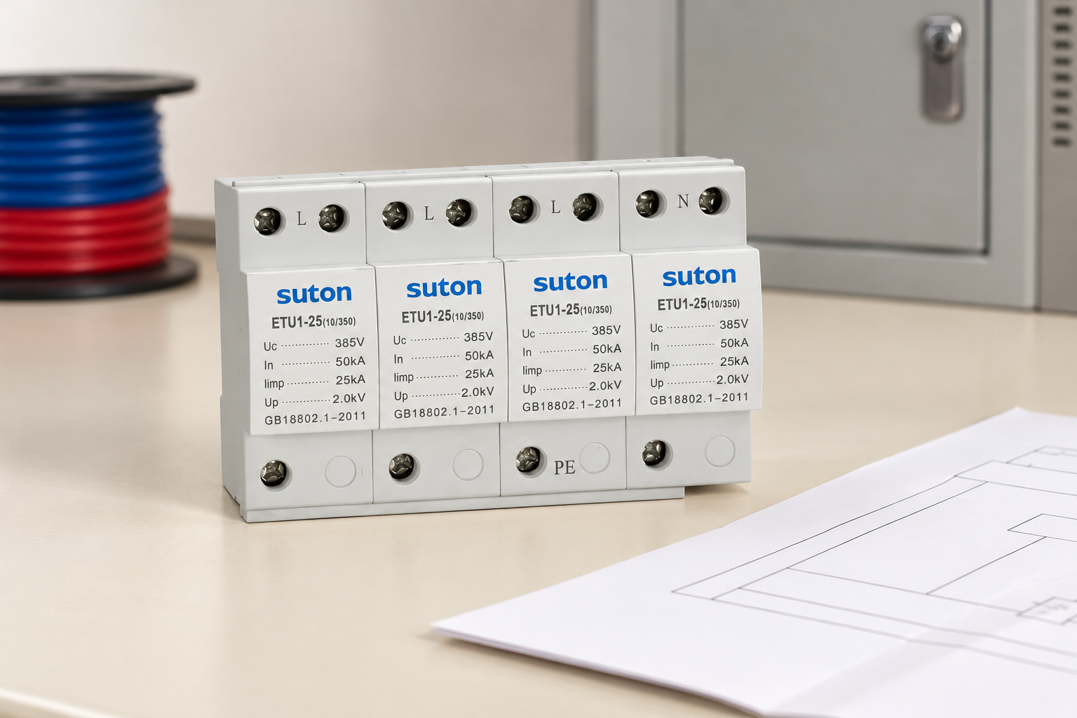
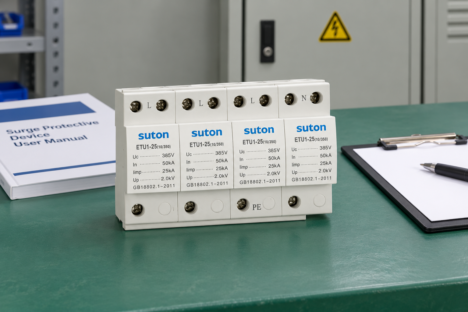
O SUTON ETU1 product family is the reference for the illustrations in this article. Request the exact version supported for the panel's voltage, protective paths and duty. Do not use the exterior image to infer monitoring options, approvals or internal technology.
Send the panel drawing, supply modes, destination requirements, equipment list, available fault conditions and proposed branch protection. Include signal interfaces, layout constraints and maintenance needs. Ask for the supported model, connection diagram, backup conditions, coordination evidence and replacement instructions in one traceable response.
Utilizar Supondo que você tenha um problema com o seu produto ou serviço, entre em contato com o suporte do SUTON. to resolve incomplete product information. The final specification should identify a documented arrangement that can be purchased, installed, monitored and maintained consistently. This is more useful than an isolated surge-current target with no record of the conditions it must serve.
Perguntas frequentes
Is the highest surge-current rating the best choice for a control panel?
Not by itself. Suitability also depends on operating voltage, protective paths, classification, protection characteristics, fault duty, backup protection and installation. Compare complete supported arrangements against the same panel requirements.
Does a power SPD protect every communication interface?
No. It protects the paths declared for that device. Communication and field circuits may need separate interface-specific protection and a coordinated bonding assessment. Identify every relevant incoming service in the panel design.
Can an SPD label establish compliance for the entire panel?
No. The label and supporting evidence apply within their stated scope and conditions. The complete panel, destination requirements and installed arrangement need their own assessment. Obtain exact model documentation and assembly review.
Vídeo educativo
Surge Protection – Fundamentals by IAEI – The Electrical Enforcement Authority. General surge-protection education; it does not establish a SUTON internal circuit or model-specific installation approval.