Busbar clearance and creepage distance describe two different insulation paths: clearance is the shortest distance through air, while creepage follows the surface of insulating material. In an LV panel, both must suit the electrical duty, environment, insulation system and applicable assembly requirements. There is no reliable universal spacing value for every 400 V, 690 V or other low-voltage arrangement. Before approving a layout, identify the voltage and insulation-coordination inputs, determine the applicable requirements and verify the worst-case manufactured geometry. An external product photograph cannot establish internal compliance.
Understand the two paths before measuring
Clearance is evaluated through air between relevant conductive parts. Those parts can include adjacent phases, live metal and an earthed enclosure, or conductors and nearby metal hardware. The critical path may be at a corner, projecting fastener or terminal rather than between the broad flat faces of the busbars. A drawing showing only center-to-center spacing can therefore hide the limiting gap.
Creepage follows an insulating surface between conductive parts. Its shortest route can pass around a support, along a terminal block or across a molded housing. The path depends on the actual surface geometry and the applicable measurement rules. It is not simply the visible straight-line distance across a photograph, and it is not automatically equal to clearance.
Solid insulation is another part of the design. A sleeve, coating or barrier should not be credited as equivalent to an air gap without confirming the relevant insulation requirements and construction evidence. Likewise, adding a plastic sheet between bars does not automatically solve both clearance and creepage. The installed barrier geometry, material and fastening arrangement need assessment as part of the complete system.
Establish the applicable standard and design inputs
IEC 61439-1 provides general requirements for low-voltage assemblies and works with the relevant assembly-specific part. IEC 60664-1 with its 2025 amendment addresses insulation coordination, including air gaps, surface paths and solid insulation. Identify the edition required by the contract and how it applies to the actual assembly. A public catalog description establishes scope, not a project-specific minimum distance.
For clearance, the engineering assessment includes impulse withstand duty, overvoltage conditions, altitude and the relevant electric-field and installation assumptions. For creepage, working voltage, pollution conditions and the insulating material's tracking performance matter. Insulation function also matters: functional, basic or other required insulation cannot be treated interchangeably without design justification.
Record these inputs in a review sheet before discussing dimensions. If a supplier gives a single spacing number without the associated assumptions, ask what it represents and which paths it covers. A number used inside one verified device does not automatically apply between exposed busbars in a different enclosure or environmental condition.
Use a path register rather than one panel-wide number
List the relevant insulation interfaces on the assembly drawing. Give each path an identifier, the two conductive parts involved, the insulation function, the requirement source and the minimum finished dimension. Separate phase-to-phase paths from live-to-earth paths and include incoming connections, outgoing terminals and removable covers where relevant. This makes review and factory inspection traceable.
Use the actual finished geometry. A nominal bar spacing of 20 mm with a 6 mm projection into the gap leaves 14 mm locally in a simple illustrative arrangement. That subtraction only describes geometry; it is not an acceptable clearance determination. Whether 14 mm is sufficient depends on the identified electrical requirements and measurement method. Keep arithmetic examples separate from compliance decisions.
Apply tolerances in the direction that reduces the available distance. Bar position, support placement, fastener projection, enclosure alignment and conductor termination can all affect the shortest path. A layout that passes only at ideal nominal dimensions is difficult to manufacture consistently. Specify inspection points that correspond to the actual limiting paths rather than convenient locations with generous space.
| Rever item | Information required | Verification record |
|---|---|---|
| Air paths | Relevant conductive parts and impulse duty | Critical clearance paths and requirement source |
| Surface paths | Working voltage and actual surface route | Creepage paths and approved measurement rules |
| Ambiente | Pollution conditions and site altitude | Documented assumptions and applicable corrections |
| Materials | Insulator identity and tracking data | Approved material evidence |
| Geometry | Fasteners, lugs, barriers and tolerances | Worst-case finished dimensions |
| Assembly identity | Order code and drawing revision | Matching design and inspection records |
This table is an evidence checklist, not a replacement for the distance tables and measurement rules in the applicable standards. It helps the purchaser identify missing inputs and drawings. The final acceptance record should state both the required minimum and the measured or otherwise verified result for each relevant path.
Assess pollution, moisture and insulating materials
The relevant pollution condition is the local environment of the insulation, not simply the building address or a broad description such as industrial use. Dust, conductive deposits and condensation can change the behavior of an insulating surface. A clean factory inspection does not establish the conditions that will exist after installation or maintenance.
Ask how the enclosure and installation arrangement maintain the assumed environment. Cable entries, ventilation, door seals and internal heat management can affect contamination or moisture exposure. Do not assume an ingress-protection label alone answers every insulation-coordination question. The project needs compatible construction, installation conditions and maintenance expectations.
Material tracking performance must come from identified material data or relevant component evidence. Appearance, color and thickness do not establish a material group or comparative tracking index. If a support material changes during manufacturing, review the substitution before acceptance. A mechanically similar replacement can have different electrical properties and affect the design basis.
Check altitude and transient duty explicitly
Altitude affects the behavior of air insulation. If the site is outside the assumed range, confirm the correction and verification required by the applicable rules. Do not apply an altitude correction to every distance indiscriminately: air clearance, surface creepage and solid insulation are assessed through their relevant requirements. The responsible designer should document the method used.
Transient duty also needs a defined basis. Nominal operating voltage alone does not describe every impulse stress a panel can experience. Supply arrangement, equipment location and coordinated protection form part of the assessment. A surge protective device should not be assumed to authorize arbitrary spacing reductions without an engineering basis and evidence that all relevant conditions are satisfied.
Keep any application limits with the delivered assembly documentation. If the same panel design is exported to a higher-altitude site or a different installation environment, the previous acceptance may need review. A quotation should state the installation conditions it covers so that the buyer does not unknowingly change the insulation assumptions after purchase.
Review assembly changes and service positions
Consider the installed conductor shape and its permitted movement. Cable lugs, washers, flexible links and terminal shields can create different limiting paths from the bare busbar drawing. Verify the approved termination arrangement, not an empty cabinet before incoming and outgoing conductors are installed. Installation instructions should preserve the intended geometry.
Where equipment has adjustable or removable parts, identify which positions are covered by the design and relevant standards. A barrier that is correctly installed in normal service may be displaced during maintenance. Do not infer that every temporary service position has the same electrical safety properties. Follow the manufacturer's isolation and access instructions rather than testing spacing by approaching live parts.
Thermal expansion, mechanical loading and fault forces belong in the broader design review. The Guia de resistência de curto-circuito da barra de distribuição explains why supports and the verified configuration matter. Do not treat an initial static gap as proof of the assembly's behavior under every required mechanical and electrical condition.
Review the actual SUTON enclosure and supporting drawings
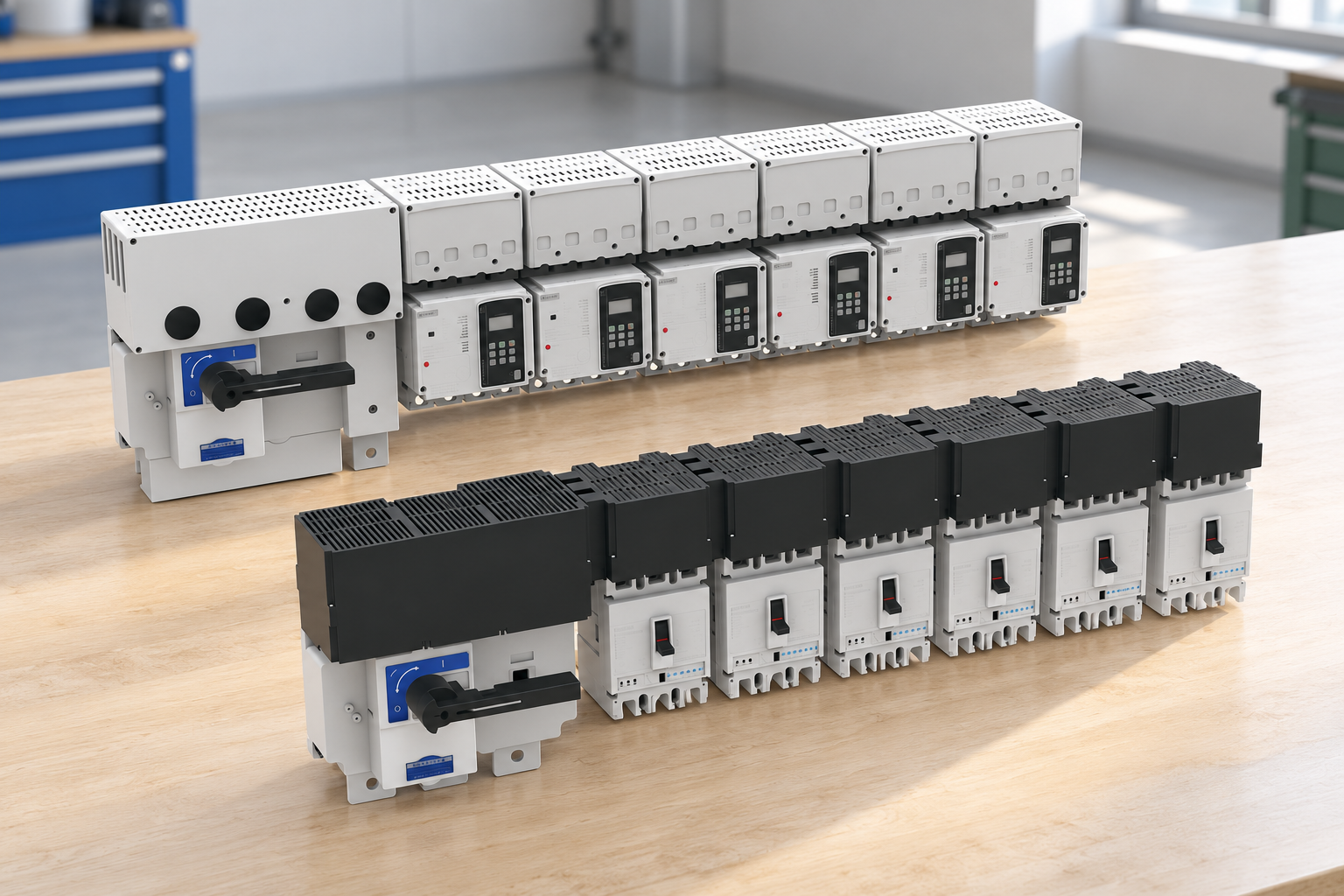
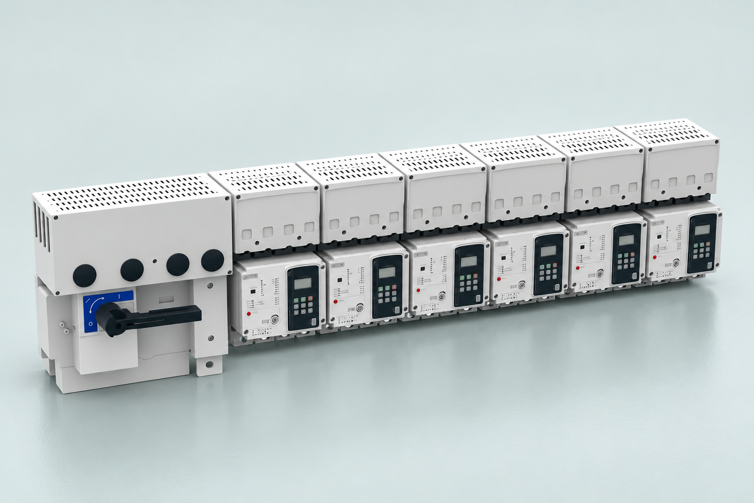
O SUTON ETFZX sistema de quadro de distribuição provides a real product reference for discussing enclosed distribution equipment. The illustrations show external housings and devices. They do not expose internal air paths, insulating-surface routes or support materials, and they must not be used to measure a claimed internal minimum distance.
Send the supplier the supply voltage and system, project standard, impulse requirements, site altitude and intended environment. Request an order-specific drawing, declared insulation characteristics and the applicable verification records. Where detailed internal drawings are controlled, agree on a suitable compliance statement and inspection evidence that still identifies the supplied configuration and relevant assumptions.
Coordinate these records with the Guia do sistema de barras de distribuição para construtores de painéis, busbar connection guide e temperature-rise review. Adequate spacing does not establish thermal rating or connection quality. The purchase decision should bring these separate requirements together for one identified assembly.
Close the inspection with a traceable acceptance record
A useful final record lists drawing revision, supplied order code, approved materials, critical paths and the verification method. Include relevant photographs or inspection measurements where appropriate, but do not substitute a general photograph for dimensions that cannot be seen. Record deviations and their approved resolution before releasing the assembly for installation.
For later modifications, retain the same path identifiers and review any new conductive part, barrier change or support substitution. Adding a monitoring cable or replacing a terminal can alter a limiting path even when the main bars stay in place. A small change deserves a focused review when it affects the original insulation assumptions.
Perguntas frequentes
Can one minimum gap be used for every LV panel?
No. Required air and surface distances depend on the electrical duty, insulation function, environment, materials and applicable standard. Establish those inputs and identify the relevant paths before approving dimensions for a specific assembly.
Does adding a barrier automatically correct insufficient spacing?
No. A barrier changes the insulation arrangement and needs assessment of its material, geometry, fastening and applicable verification. It may affect air paths, surface paths and solid-insulation requirements differently. Use an approved design change with matching evidence.
Can creepage and clearance be checked from a catalog photo?
Usually not for internal paths in an enclosed assembly. Perspective, hidden conductive projections and concealed surface routes prevent a reliable determination. Request the appropriate drawing and verification record, and inspect the finished configuration using the approved method.
Vídeo educativo
Mod-01 Lec-16 Dielectric (Insulating) Solids by nptelhrd. This IIT Madras/NPTEL lecture explains dielectric materials as background for insulation behavior. It does not provide assembly spacing values or replace insulation-coordination verification.