


motor circuit protector vs circuit breaker: A motor circuit protector is generally applied as part of a coordinated motor branch-circuit assembly and often focuses on short-circuit protection. A general circuit breaker may provide broader overcurrent protection, depending on its type and application. This guide explains a defensible inspection and selection workflow for panel builders, contractors, facility teams, and technical buyers. It is not an energized-work instruction. Apply the adopted local rules, the project study, and the exact manufacturer documentation.
Quick answer and decision table
| Check | Motor circuit protector | General circuit breaker |
| Application | Coordinated motor starter assembly | Feeders, branches, equipment, or motors as declared |
| Overload function | Often supplied by a separate overload relay | May include overload protection |
| Adjustment | Set within approved motor coordination data | Set or selected for conductor and load protection |
| Evidence | Starter combination and short-circuit rating | Device curve, fault rating, and application data |
Safety basis: OSHA 1910.303, OSHA 1910.333, and NIOSH electrical safety guidance. Project requirements may be stricter.

What the observation does—and does not—prove
A motor protector should not be treated as a stand-alone substitute unless the complete approved assembly supports that use. A useful diagnosis separates observation from conclusion. Record what was seen, the operating state, the load and environmental conditions, and the exact device identity. Then decide which additional checks are needed. A handle position, meter reading, temperature image, or visible connection is evidence, but each has limits.
Motor starting current, overload relay class, contactor duty, conductor protection, and available fault current must be reviewed together. The responsible person should compare the result with the single-line diagram, panel schedule, conductor information, protective-device curve, and applicable instructions. If those records disagree with the installation, stop and resolve the discrepancy before treating the circuit as accepted.
Start with a safe work boundary
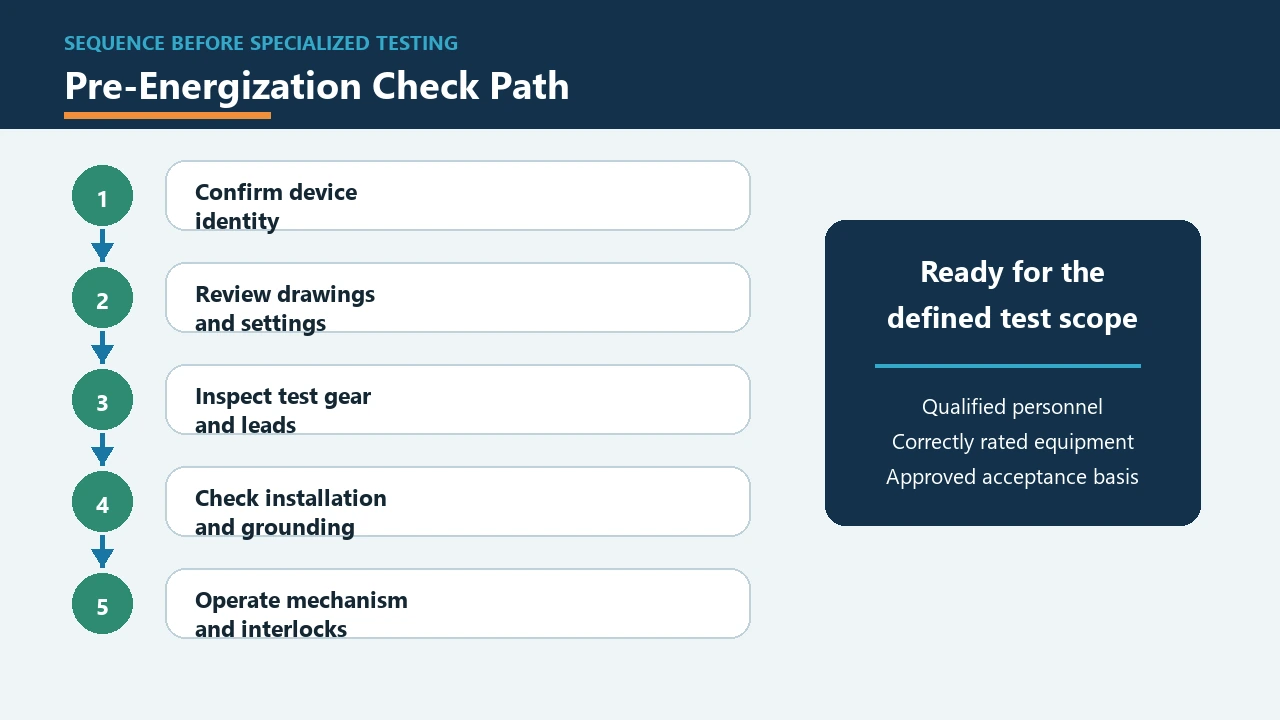
Electrical panels can contain shock, arc-flash, and stored-energy hazards. De-energize exposed live parts before work unless a justified exception and an approved energized-work procedure apply. Identify every source, interrupt the load by the approved sequence, isolate it, apply lockout/tagout, release or restrain stored energy, and verify the required condition with an adequately rated instrument.
The test instrument, leads, probes, and accessories must suit the installation category and voltage. Inspect them before use and prove the tester according to the site method. Resistance and continuity functions must not be applied to an energized circuit. If a task requires exposure to live parts, only qualified people using the required risk controls may perform it.
Identify the exact breaker and circuit
Record manufacturer, catalog number, frame and trip rating, poles, voltage, breaking capacity, trip-unit type, settings, accessories, and upstream/downstream devices. Note conductor size, material, terminal arrangement, enclosure temperature, mounting orientation, and visible damage. Similar-looking breakers can have different terminal permissions, trip characteristics, and interruption ratings.
Trace the protected load rather than trusting an old label. Check whether control power, generators, photovoltaic sources, UPS equipment, or interconnected systems can backfeed the circuit. For multi-pole equipment, understand how all poles and neutrals are handled. This identity work prevents a technically correct test from being applied to the wrong circuit.
A practical investigation sequence
- Define the symptom or decision. State the question in one sentence.
- Collect records. Obtain drawings, schedules, studies, instructions, and maintenance history.
- Establish safe conditions. Follow the approved isolation and verification procedure.
- Inspect before testing. Look for heat damage, contamination, loose parts, unsuitable conductors, and unauthorized changes.
- Choose a test that answers the question. Write down what a pass or fail will mean before measuring.
- Compare with declared data. Use exact product and project limits, not a value copied from another breaker.
- Correct the cause. Do not merely reset, retighten, or replace without addressing the circuit condition.
- Document and review. Record final configuration, settings, tests, and approval.
Interpret results in the complete protection system
A breaker is one part of a system that includes the source, conductors, terminals, enclosure, load, grounding arrangement, upstream protection, and downstream equipment. A result that looks acceptable in isolation may still be unsuitable when available fault current, conductor ampacity, ambient derating, motor starting, harmonics, or selectivity is considered.
Keep continuous-current duty separate from short-circuit duty. The printed ampere rating does not establish breaking capacity, and breaking capacity does not prove that the trip characteristic protects a particular conductor or load. Where adjustable protection is used, every setting should match the approved coordination study and be verified during commissioning.
Common mistakes to avoid
- Increasing the breaker rating to stop tripping without checking conductor protection.
- Assuming a continuity or voltage reading proves the complete protective function.
- Working from a family brochure instead of the exact catalog number and accessory diagram.
- Reusing torque, conductor, or test values from a different frame or terminal.
- Ignoring environmental heat, grouping, enclosure condition, and connection resistance.
- Resetting after a serious fault without inspection and fault-cause investigation.
- Treating remote indication as proof of electrical isolation.
Information to request from a supplier
For a replacement or new panel, send system voltage and frequency, AC or DC duty, poles and neutral arrangement, normal current, calculated fault current, required breaking capacity, trip function and settings, load characteristics, terminals and conductor details, accessories, control voltage, mounting, ambient conditions, and the documentation required by the contract.
Ask for a completed compliance schedule, exact datasheets, dimensional drawings, wiring diagrams, declared standards, and routine or project test records. For relevant low-voltage products, review the SUTON modular DIN-rail range and verify the offered configuration against the actual project. The circuit breaker types guide provides the parent overview.
Build a record another engineer can audit
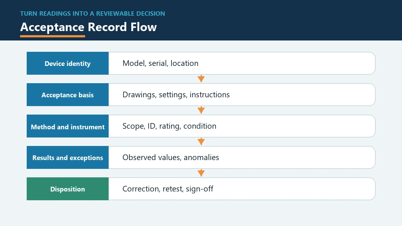
A useful report should let a reviewer reconstruct the decision without visiting the panel. Include the circuit reference, equipment location, date, work authorization, persons involved, isolation points, instrument identity, instrument verification status, ambient condition, load state, observations, measured values with units, photographs, and the exact acceptance criterion. When a value comes from a drawing, study, standard, or manufacturer instruction, identify that source and revision. Do not write “normal” or “good” without explaining the comparison.
Separate as-found and as-left conditions. If a conductor was moved, a terminal was remade, a setting was changed, or a breaker was replaced, record both states and the approval for the change. List unresolved exceptions and the safe interim condition. A clear exception log prevents a temporary observation from becoming an undocumented permanent acceptance.
When replacement is considered
Replacement should address the cause and preserve the engineered protection scheme. Confirm physical fit, pole arrangement, voltage, frequency, continuous current, short-circuit duty, trip characteristic, terminals, accessories, isolation function, environmental limits, and coordination. A replacement that fits the opening but changes the instantaneous region, neutral treatment, control voltage, or interlock can create a new risk.
For obsolete equipment, decide whether an approved direct replacement, engineered retrofit, or switchboard renewal is appropriate. The decision should consider equipment condition, available manufacturer support, fault-duty changes, spare parts, downtime, maintainability, and the ability to produce a complete technical file. Procurement price alone is not a sufficient engineering criterion.
Commissioning after corrective work
After corrective work, repeat the inspections and tests that are affected by the change. Verify device identity and settings, conductor placement, terminal work, mechanical operation, auxiliary functions, labels, barriers, and panel condition. Confirm that temporary grounds, tools, jumpers, and test leads have been removed. Restore covers and interlocks before the approved energization sequence.
Observe the circuit under a controlled operating condition when the procedure requires it. Compare load and temperature behavior with the earlier symptom, but do not use a short observation as proof of long-term performance. Close the record only after the responsible person accepts the evidence and updates drawings, schedules, maintenance history, and spare-parts information.
Questions for the technical review
Before approval, ask whether the proposed conclusion explains every observed symptom and whether another credible cause remains untested. Confirm that the measuring method was suitable, the instrument uncertainty was acceptable for the decision, and the circuit was in the operating state assumed by the procedure. Check whether seasonal temperature, production loading, motor starts, standby sources, or recent modifications could change the result at another time.
The review should also ask what happens after the next fault. Identify who may reset or operate the device, which inspection is required, what spare is approved, and which event triggers escalation to an engineering study or equipment replacement. These questions turn a one-time repair into a maintainable protection strategy. They are especially important when the original documentation is incomplete or when several generations of equipment share one panel.
Related technical guides
- Circuit breaker trip investigation
- Circuit breaker commissioning workflow
- Main circuit breaker selection
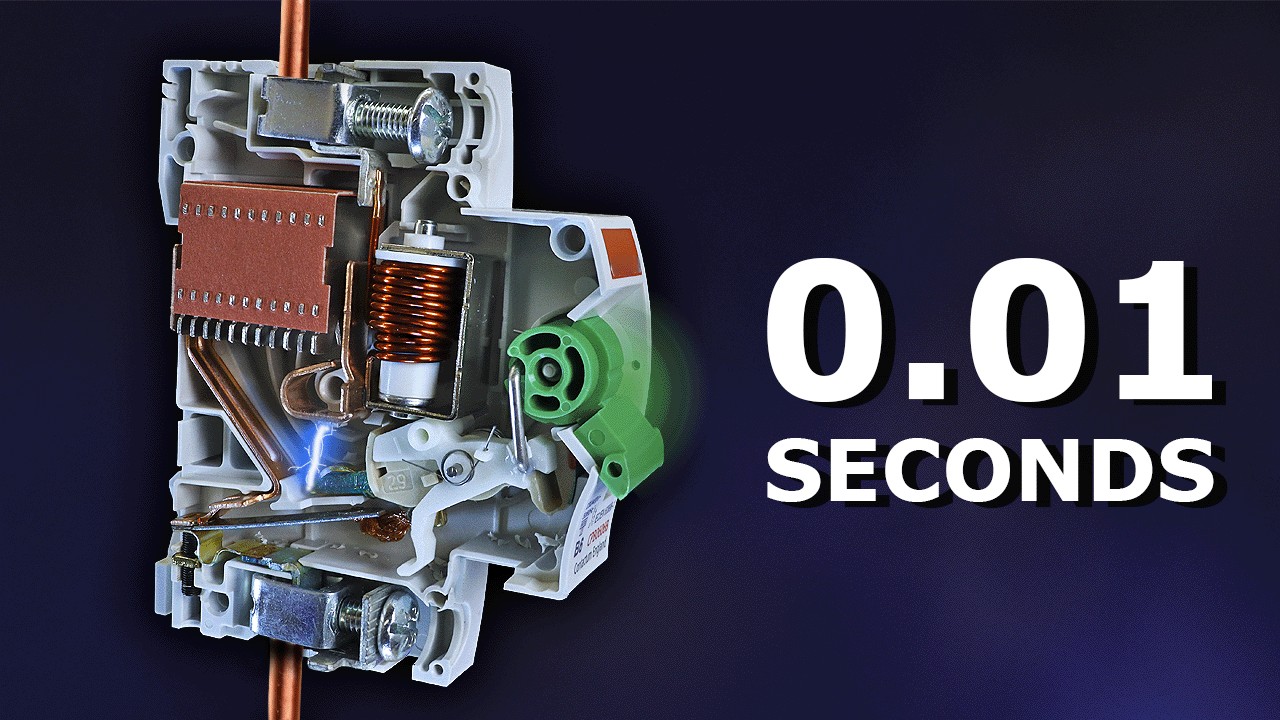
Educational video: circuit breaker fundamentals
This neutral explainer from The Engineering Mindset supports the operating-principle discussion and does not replace project calculations.
Frequently asked questions
Is an MCP the same as an MCCB?
No. Names, functions, and approvals differ; use exact manufacturer and assembly documentation.
Who protects the motor from overload?
Often a dedicated overload relay, but the complete starter design determines the function.
Can a normal breaker protect a motor?
It can be part of a compliant design when ratings, starting behavior, overload protection, and coordination are correct.
Final checklist
Confirm the circuit identity, safe work boundary, exact device data, conductor and terminal condition, load and fault duty, selected test method, interpretation limits, corrective action, and final record. When any item is uncertain, keep the equipment in a safe state and refer the decision to the qualified designer or responsible authority.